
Rainier AWD L6-4.2L (2007)
repairs.
3.
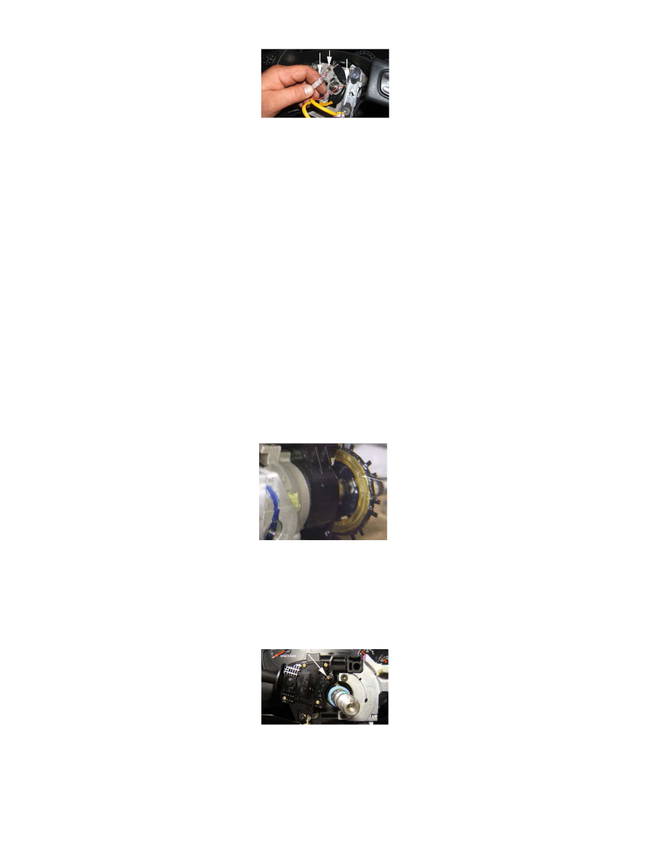
Remove the Inflatable Restraint Steering Wheel Module using the procedure found in Service Information. Remove the horn contacts from the
steering wheel. Clean the brass contact on the end of the red wires with an abrasive pad. If possible, remove any contamination present on the
mating contact on the cancel cam (inside the black tube). Also clean the four copper rivets embedded in the steering wheel frame. Apply GM
Dielectric Lubricant to all the contacts to protect against reoccurrence of the corrosion. Refer to the graphic.
4.
Reinstall the horn contacts and the Inflatable Restraint Steering Wheel Module and test for proper operation of the horn pad. Test for proper
operation of the horn pad through the entire steering wheel rotation. Does the horn pad work properly?
^
Yes - repair is complete.
^
No - proceed with step 5.
5.
Is the inoperative condition only present at certain steering wheel positions?
^
Yes - proceed with step 6.
^
No - proceed with step 9.
6.
Remove the steering column trim covers. Position the steering wheel on a dead spot. Ground a test light to the steering column frame close to the
steering wheel. Probe the surface of the turn signal cancel cam with the test light. Does grounding the cam activate the horn?
^
Yes - this may mean that the contact of the cancel cam that mates to the horn contact wiring harness contact, may not be clean enough or that
the cancel cam may need to be replaced. Repair as necessary. Procedure complete.
^
No - proceed with step 7.Turn Signal Cancel Cam:
7.
Disconnect the wiring harness that goes to the top of the multi-function switch (connector X1). Using the grounded test light, touch the harness
connection for pin G. Does grounding the pin activate the horn?
^
Yes - proceed with step 8.
^
No - try grounding the test light on a known good ground. If this activates the horn, proceed to step 9. If not, investigate a possible condition
with the wiring harness or BCM with appropriate SI documents.
8.
The condition lies either in the multi-function switch or the interface between the multi-function switch and the cancel cam. In some cases,
removing the multi-function switch and clearing the horn contact that mates with the cancel cam (refer to the graphic) of debris and reinstalling the
switch will eliminate the condition. In other cases, the cancel cam may be losing contact with the multi-function switch contact. If distortion in the
cancel cam is present, it may be necessary to replace the cancel cam. Repair as necessary. Procedure complete.
9.
Remove the left side IP insulator (refer to Instrument Panel Insulator Panel Replacement found in SI) so it can be moved aside enough to see the