
Rainier AWD L6-4.2L VIN S (2005)
Throttle Body: Service and Repair
THROTTLE BODY ASSEMBLY REPLACEMENT
REMOVAL PROCEDURE
1. Remove the resonator assembly.
2. Remove the evaporative emission (EVAP) canister purge line from the throttle body.
3. Disconnect the throttle body electrical connector.
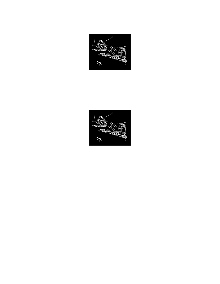
4. Remove the throttle body assembly retaining bolts (1).
5. Remove the throttle body assembly (2) and the gasket from the intake manifold.
6. Clean the gasket surface.
INSTALLATION PROCEDURE
1. Install the throttle body assembly (2) to the intake manifold with the gasket.
2. Add sealer GM P/N 12346004 (Canadian P/N 10953480) to the throttle control module bolt threads.
3. Install the throttle body assembly retaining bolts (1).
NOTE: Refer to Fastener Notice in Service Precautions.
Tighten the bolts to 10 N.m (89 lb in).
4. Connect the throttle body electrical connector.
5. Install the EVAP canister purge line to the throttle body.
6. Install the resonator assembly.