
Rainier AWD L6-4.2L VIN S (2005)
5.
Using the J-35616-5, attach the RED lead from the other jumper harness to the Motor Control B terminal (pin E - wire color red) of the transfer
case encoder motor (actuator) wiring harness connector.
6.
Using the J-35616-5, attach the BLACK lead from the jumper harness to the Motor Control A terminal (pin D - wire color black) of the transfer
case encoder motor (actuator) wiring harness connector.
7.
Touch the battery terminals of the second 9-volt battery to the battery terminals of the second jumper harness. This will rotate the encoder motor (
actuator) shaft in either a clockwise or counterclockwise rotation depending on battery orientation.
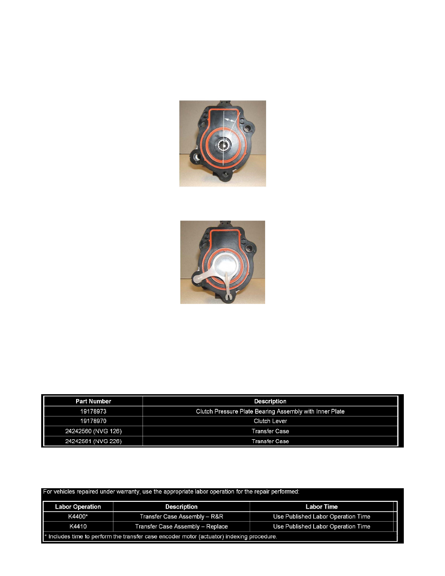
8.
Using the 9-volt battery, rotate the encoder motor (actuator) shaft until the keyway on the motor shaft is between the reference lines as shown in
the picture. This orientates the encoder motor (actuator) to NETURAL for ease of assembly.
Note:
If available, another option is to rotate the encoder motor (actuator) shaft until a shipping plug from a new encoder motor (actuator) can be
installed.
9.
Wiggle the control actuator lever shaft of the transfer case by hand to find the low point of the cam.
10.
Install the encoder motor (actuator) on the control actuator lever shaft of the transfer case.
11.
After installation, the transfer case will perform a learn procedure upon a requested MODE change.
Parts Information
For warranty claims, submit batteries as parts.