
Reatta V6-231 3.8L VIN C SFI (1990)
Electrical Flow Of Data
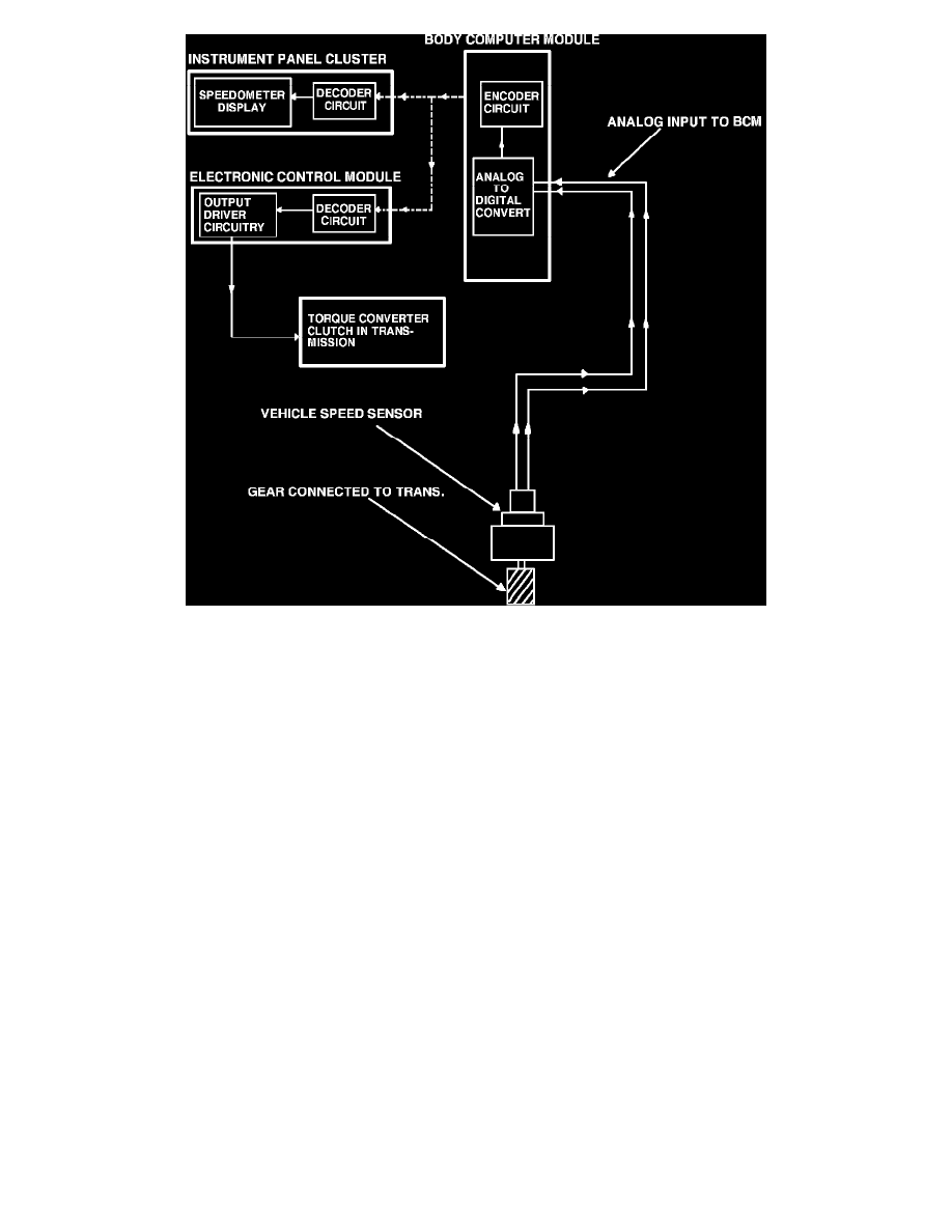
A practical example of this process is as follows:
The BCM receives vehicle speed by monitoring the vehicle speed sensor, the speed sensors output is an analog signal (AC voltage). The BCM then
converts this signal to a digital signal and assigns the addresses of the ECM and the IPC. The BCM now sends the signal out onto the data line. The
ECM/PCM receives the vehicle speed and uses this input to control the transmission torque converter and other related engine functions. The IPC
receives the input and displays vehicle speed on the instrument panel to inform the driver. Since vehicle speed is not needed for proper operation of the
Heater A/C programmer and the ECC panel, the BCM did not assign their addresses to the information.
The data communication gives the BCM control over the ECM's/PCM's self diagnostic capabilities in addition to its own. The BCM controls body
sub-systems such as cooling fan control, fuel data display, outside temperature display, rear defogger, retained accessory power, self-diagnostics, and
vacuum fluorescent display dimming. In order to access and control the BCM self-diagnostic features, the Instrument Panel Cluster (IPC) and Electronic
Climate Control panel (ECC) are used.