
Reatta V6-231 3.8L VIN C SFI (1990)
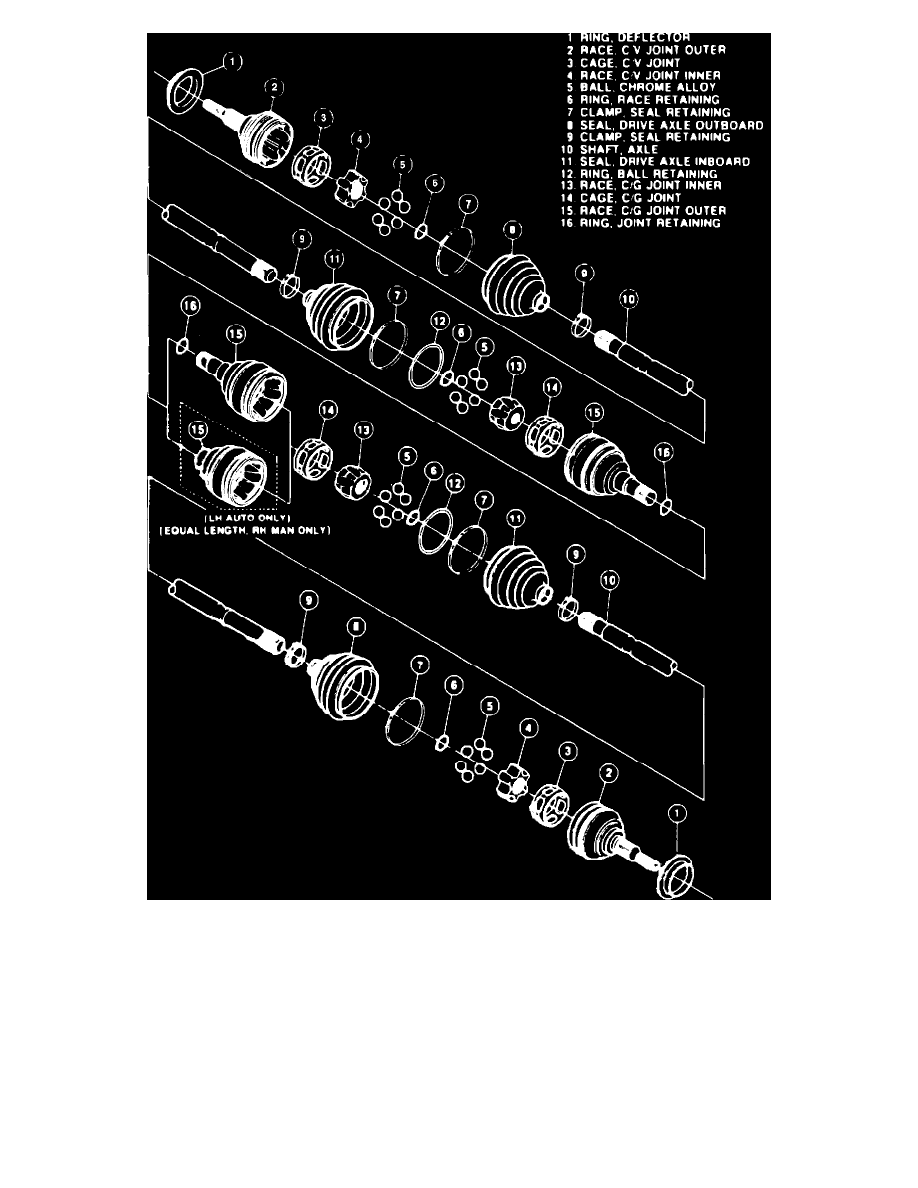
Fig. 4 Exploded View Of Cross-groove Design Drive Axle. Models w/Manual Transmission Except Geo Models & LeMans
On all except Geo models and LeMans, a ball type constant velocity joint is used at the outboard end, while a tri-pot type joint is used at the inboard
end, Fig. 3. Snap rings are used to lock the male splines of the axle shafts into the transaxle gears, except for the left side inboard joint used with the
automatic transaxles. The left side inboard joint used on automatic transaxle models utilizes a female spline which installs over a transaxle stub shaft.
On some manual transmissions, a constant velocity joint is used on the inboard end of the drive axle, Fig. 4.