
Regal V6-231 3.8L Turbo VIN 8 4-bbl (1983)
Valve Guide Seal: Customer Interest
Engine - Abnormal Oil Consumption or Detonation
Model Year 1983
Bulletin No. 83-51A
File In Group 60
Number 12A
Date Nov. '83
NOTE:
SUPERCEDES BULLETIN 83-51 NO. 12, GROUP 60
SUBJECT:
INTAKE VALVE SEALS
MODELS AFFECTED: ALL WITH 3.0L, 3.8L and 4.1L V-6 ENGINES VIN CODES "E, A", 3, 8, AND 4
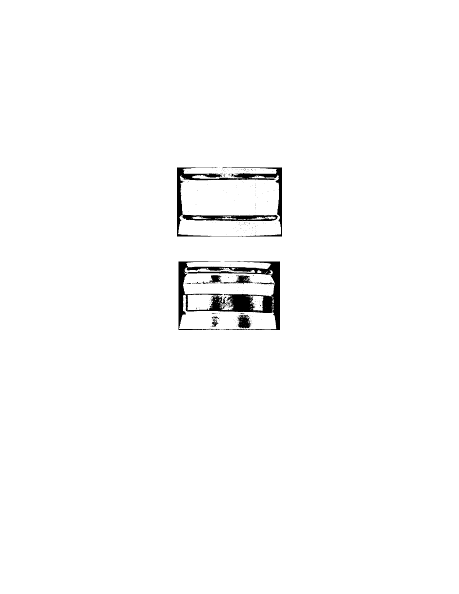
LARGER DIAMETER SEAL
SMALLER DIAMETER LATE TYPE SEAL
A new smaller diameter intake valve seal went into production approximately December 1, 1982, on 3.0L, 3.8L and 4.1L engines. (See Illustration). The
new seal will reduce the possibility of the seals lifting off the valve guide, which could result in abnormal oil consumption or detonation.
If either of these conditions is encountered, the new seals Part No. 25518390 should be installed. The seals should also be installed on the above engines
whenever engine coolant (ethylene glycol) which can deteriorate the valve seal is present in the engine oil or internal coolant loss is suspected. Since the
cylinder head valve guide outside diameter was reduced to accept the new seal, it will be necessary to rework the valve guide to the new smaller diameter
prior to its installation.
This can be done by removing the cylinder head and using a valve guide cutting tool such as the KL1440, or equivalent, which will reduce the valve
guide outside diameter to the new dimension, and is available from the following address:
*K-Line Industries, Inc. 315 Garden Avenue Holland, MI 49423 Toll Free 1-800-253-2648 (Michigan Only 1-800-632-4595)
NOTICE:
An exchange program for badly worn or used tools (less pilot) is also available through K-Line Industries. Price of rebuilt tool (part
#1443ADRT) is $17.50 plus postage. This price is based on manufacturers ability to rebuild returned unit.
Instructions For Machining Guides
1.
Remove cylinder head and valve assemblies as outlined in the service manual.
2.
Remove both intake and exhaust valves from cylinder head. (This is necessary to eliminate possibility of metal chips from cutting tool becoming
lodged in exhaust valve guide mechanism.)
3.
Insert machining tool in chuck of 1/2" electric drill (low speed drill).
4.
Place cylinder head on clean working surface, oil tool pilot and insert it into intake valve guide.