
Regal V6-231 3.8L VIN L SFI (1990)
Brake Light Switch: Service and Repair
*** UPDATED BY TSB # 90-T-78 DATED APRIL 1990
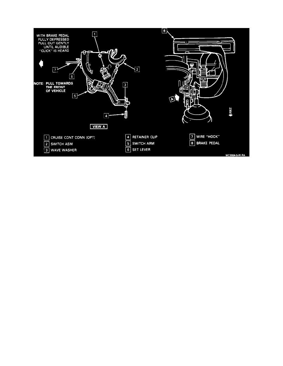
Figure 1 - Stoplamp Switch
STOPLAMP SWITCH
Figure 1
Remove or Disconnect
1.
Air cleaner assembly, if necessary to access battery cables.
2.
Negative battery cable.
3.
Left side sound insulator panel.
-
Slide steering shaft protective sleeve towards the cowl.
4.
Air distribution tube and pull down.
5.
Retainer clip which holds stoplamp switch to steering column bracket.
6.
Switch arm from pedal by pushing the arm over and off of the brake pedal pin.
-
Release switch by pulling down and releasing top snap clip.
7.
Connector position assurance (CPA) locking pins from the four wire and two wire connector.
8.
Two wire connector.
-
Two wire connector is optional cruise control equipment.
9.
Four wire connector
10.
Switch
Install or Connect
1.
Two wire connector and CPA, if equipped with cruise control.