
Regal V6-3.8L SC VIN 1 (1998)
Body Control Module (BCM) (Part 3 Of 3)
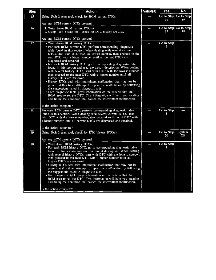
SYSTEM DESCRIPTION
The Body Control Module (BCM) Diagnostic System Check is an organized approach to identify problems associated with the BCM. The BCM
Diagnostic System Check must be the starting point for any BCM-related complaint. The BCM Diagnostic System Check will direct you to the
next logical step in diagnosing the complaint. The BCM is a very reliable component and it is not likely the cause of the malfunction. Most BCM
system malfunctions are linked to faulty wiring, connectors, and occasionally to other vehicle components. Understanding the BCM and using the
diagnostic tables correctly will reduce diagnostic time and prevent unnecessary parts replacement.
DIAGNOSTIC AIDS
^
Use a J 35616-A when probing or checking electrical connector terminals. The J 35616-A prevents terminal damage, plus checks for proper
terminal contact tension.
^
If the BCM malfunction is intermittent, refer to Intermittent and Poor Connections. See: Intermittents and Poor Connections
^
Exit all Tech 2 scan tool tests before cycling the ignition switch to the LOCK position, unless indicated by the Tech 2 scan tool. Follow the Tech 2
scan tool user's manual. Failure to follow these instructions may set DTCs, cause vehicle system malfunctions, set false DTCs, or cause Tech 2
scan tool malfunctions. DTC P1626 will set in the Powertrain Control Module (PCM) when the ignition switch is in the RUN position with the
Body Control Module (BCM) disconnected. When BCM diagnostics and repairs are completed, refer to the Engine Controls for additional
information on PCM related DTCs. See: Powertrain Management