
Regal V6-3.8L SC VIN 1 (1998)
Connecting Rod: Service and Repair
REMOVAL PROCEDURE
^
Tools Required
-
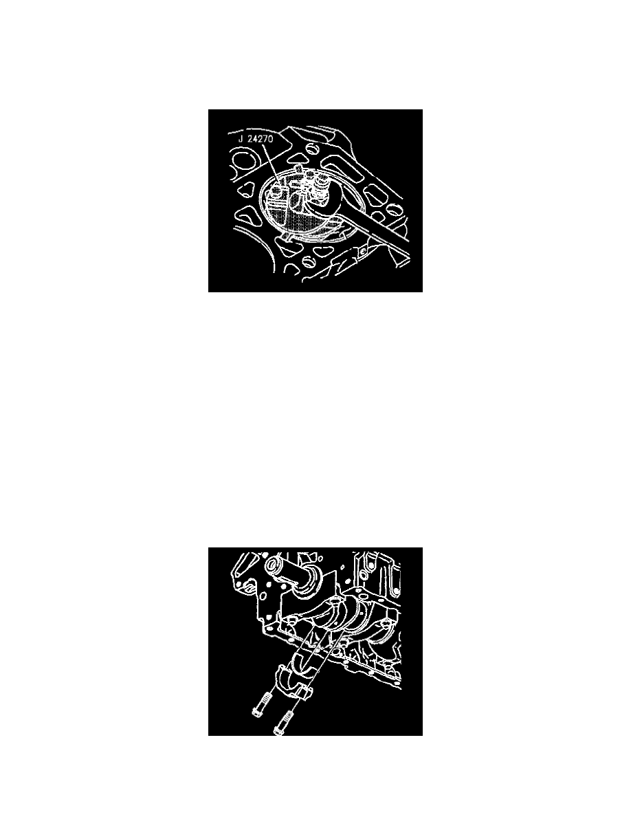
J 24270 Cylinder Bore Ridge Reamer
-
J 41507 Connecting Rod Assembly Guide
1. Remove the cylinder head. Refer to Cylinder Head Replacement (Left Front) and/or Cylinder Head Replacement (Right Pear).
Notice: Refer to Engine Emissions Notice in Service Precautions.
2. Clean the carbon from the top end of the cylinder
3. Use the following procedure in order to remove the ring ridge, as necessary:
3.1. Turn the crankshaft until the piston is at Bottom Dead Center (BDC).
3.2. Place a cloth on top of the piston.
3.3. Use the J24270 in order to remove the piston ring ridge.
3.4. Remove the J24270.
3.5. Turn the crankshaft so that the piston is at Top Dead Center (TDC).
3.6. Remove the cloth and cutting debris.
Notice: If there is a pronounced ridge at the top of the piston travel, the ridge must be removed with a ridge reamer before the piston and
connecting rod assembly are removed. Applying force may break the piston rings or damage the piston.
4. Remove the oil pan.
5. Turn the crankshaft to Bottom Dead Center (BDC).
6. Mark the piston with the number of the cylinder from which it is being removed.
7. Mark the connecting rod and the rod cap so that they can be assembled correctly.
8. Remove the connecting rod bolts.
9. Remove the connecting rod cap and lower connecting rod bearing.
10. Install the J 41507 on the connecting rod.