
Regal V6-3.8L VIN K (1997)
Engine Control Module: Description and Operation
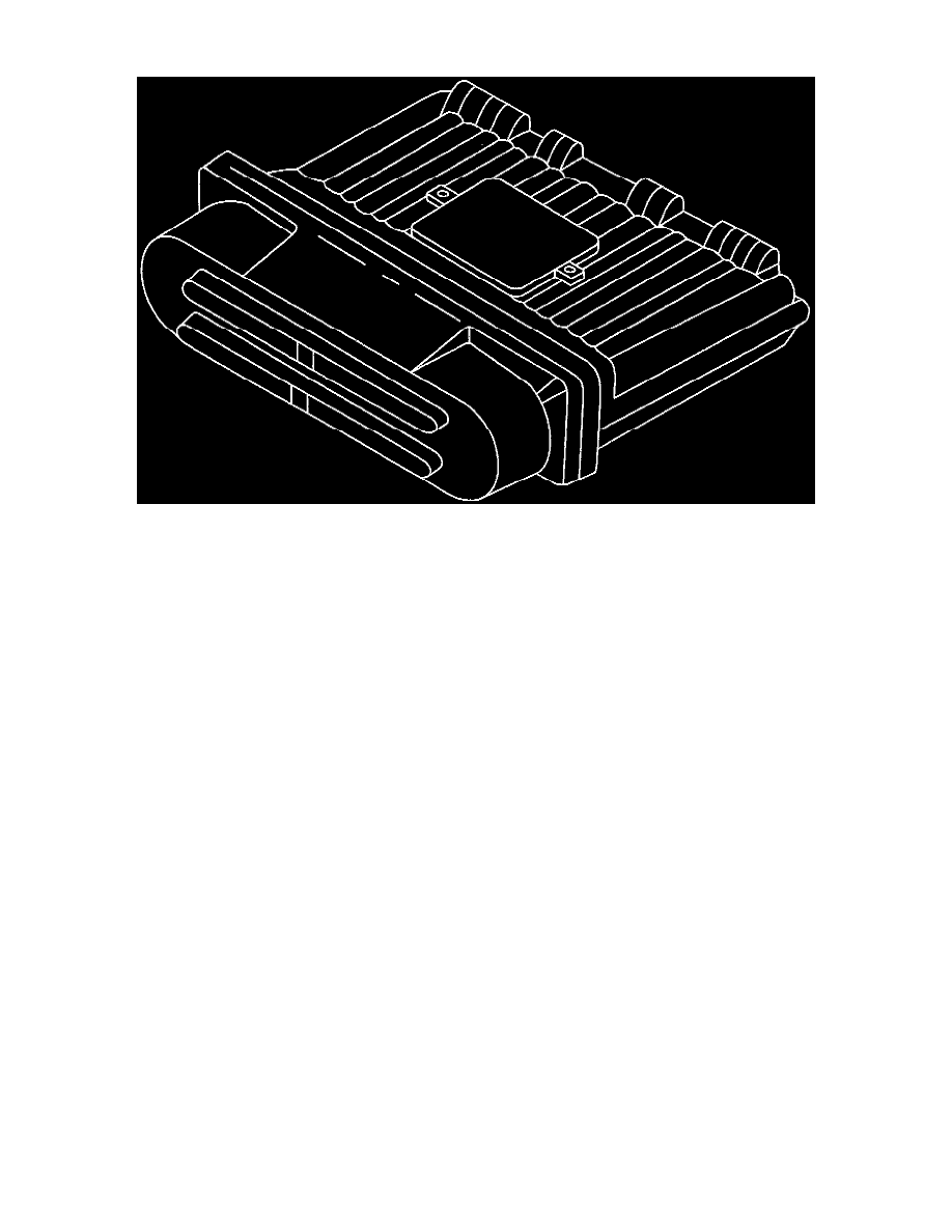
Figure C1-1 - Powertrain Control Module (PCM)
DESCRIPTION
The Powertrain Control Module (PCM) is the control center of the vehicle. It controls the following items:
-
Fuel metering system.
-
Transaxle/transmission shifting.
-
Ignition timing.
-
On-board diagnostics for powertrain functions.
It constantly looks at the information from various sensors, and controls the systems that affect vehicle performance. The PCM also performs the
diagnostic function of the system. It can recognize operational problems, alert the driver through the Malfunction Indicator Lamp (MIL), and store
diagnostic trouble codes which identify the problem areas to aid the technician in making repairs.
The type of PCM used is a PCM 32U. For service, the PCM consists of two parts: a controller (the PCM without the Knock Sensor module) and the
Knock Sensor module.
3X REFERENCE PCM INPUT
From the ignition control module, the PCM uses this signal to calculate engine RPM and crankshaft position at engine speeds above 1200 RPM. The
PCM also uses the pulses on this circuit to initiate injector pulses. If the PCM receives no pulses on this circuit, DTC P1374 will set and the PCM will
use the 18X reference signal circuit for fuel and ignition control. The engine will continue to start and run using the 18X reference signal only.
18X REFERENCE PCM INPUT
From the ignition control module, the PCM uses this signal to calculate engine RPM and crankshaft position at engine speeds below 1200 RPM. The
PCM also uses the pulses on this circuit to initiate injector pulses. If the PCM receives no pulses on this circuit, DTC P0336 will set and the PCM will
use the 3X reference signal circuit at all times for fuel and ignition control. The engine will continue to start and run using the 3X reference signal only.
REFERENCE LOW
This is a ground circuit for the digital RPM counter inside the PCM, but the wire is connected to engine ground only through the ignition control module.
Although this circuit is electrically connected to the PCM, it is not connected to ground at the PCM. The PCM compares voltage pulses on the 18X and
3X reference input circuits to any on this circuit, ignoring pulses that appear on both. If the circuit is open, or connected to ground at the PCM, it may
cause poor engine performance and possibly a MIL with no DTC set.