
Regal V6-3.8L VIN K (1997)
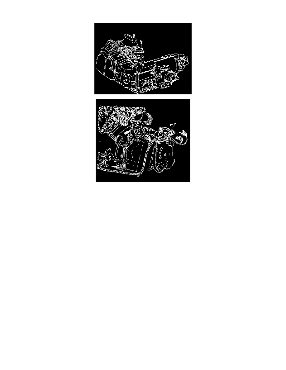
Transmission Position Switch/Sensor: Service and Repair
^
Tool Required:
-
J 41545 Park/Neutral Switch Alignment Tool
REMOVE OR DISCONNECT
1. Apply parking brake and block wheels.
2. Place vehicle in "Neutral" position.
3. Automatic transaxle range selector lever cable.
4. Electrical connector.
5. Automatic transaxle range selector lever.
6. Mounting bolts/screws.
7. Switch.
INSTALL OR CONNECT
NOTICE: Always use the correct fastener in the proper location. When you replace a fastener, use ONLY the exact part number for that application.
The manufacturer will call out those fasteners that require a replacement after removal. The manufacturer will also call out the fasteners that require
thread lockers or thread sealant. UNLESS OTHERWISE SPECIFIED, do not use supplemental coatings (paints, greases, or other corrosion inhibitors)
on threaded fasteners or fastener joint interfaces. Generally, such coatings adversely affect the fastener torque and the joint clamping force, and may
damage the fastener. When you install fasteners, use the correct tightening sequence and specifications. Following these instructions can help you
avoid damage to parts and systems.
1. Place manual shaft in "Neutral" position.
2. Align flats of manual shaft to flats in switch.
3. Mounting bolts/screws.
Important:
^
If bolt screw holes do not align with mounting boss on transaxle, verify manual shaft is in "Neutral" position. DO NOT ROTATE SWITCH.
Switch is pinned in "Neutral" position.
^
If switch has been rotated and pin broken or when using old switch, adjust as follows:
A. Assemble mounting bolts/screws loosely.