
Regal Estate Wagon V6-252 4.1L VIN 4 4-BBL (1982)
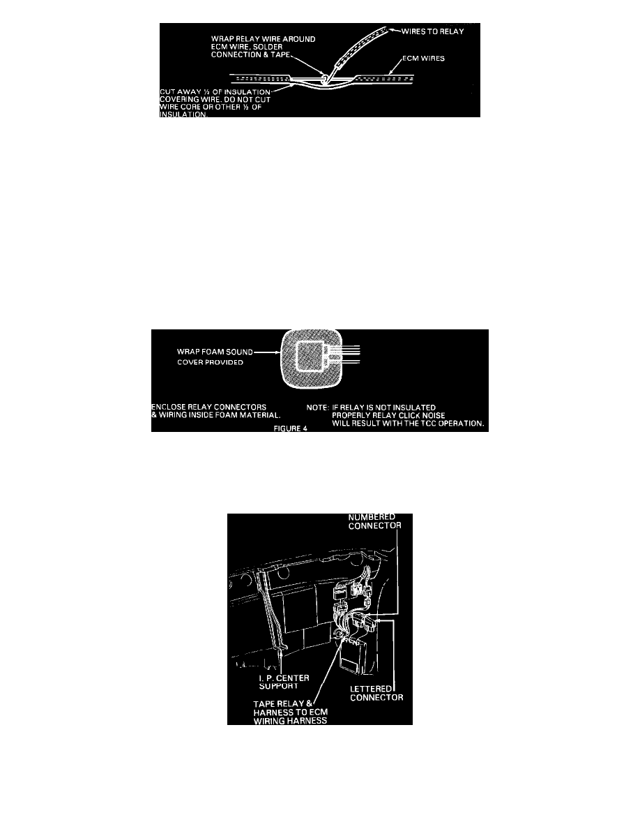
FIGURE 3
4)
Solder splice jumper harness into the following wire leads going to the lettered ECM connector of the ECM harness; See Figures 2 and 3.
Note:
Use only Rosin core solder for all solder splices.
ECM HARNESS CONNECTOR
Cavity
Circuit
Wire Color
P
422
Tan/Blk Str
T
435
Gray
C
439
Pink/Blk Str
A
450
Black
RELAY JUMPER HARNESS Wire Color
Tan/Blk Str Gray Pink/Blk Str Black
FIGURE 4 - ENCLOSE RELAY CONNECTORS & WIRING INSIDE FOAM MATERIAL.
5)
Tape each wire splice.
6)
Wrap relay in foam sound deadener provided, See Figure 4.
FIGURE 1
7)
Tape jumper harness and relay to ECM harness, See Figure 1 for locations.
8)
Install New PROM into ECM, reinstall ECM and housing.