
Regal Estate Wagon V6-252 4.1L VIN 4 4-BBL (1982)
Ball Joint: Service and Repair
Upper
On all models the upper ball joint is spring-loaded in its socket. If the ball stud has any perceptible shake or if it can be twisted with the fingers, the
ball joint should be replaced.
On all models, the lower ball joint is not spring-loaded and depends upon car weight to load the ball. The lower ball joint should never be replaced
merely because it ``feels'' loose when in an unloaded condition.
Upper ball joints on all models are riveted to the control arm and can be replaced.
Lower ball joints on all models are pressed into the control arm and can be replaced with a suitable ball joint tool. When servicing lower ball joints,
be sure to support lower control arm with a suitable jack. If lower control arm is not supported and steering knuckle is disconnected from
control arm, the heavily compressed front spring will be completely released.
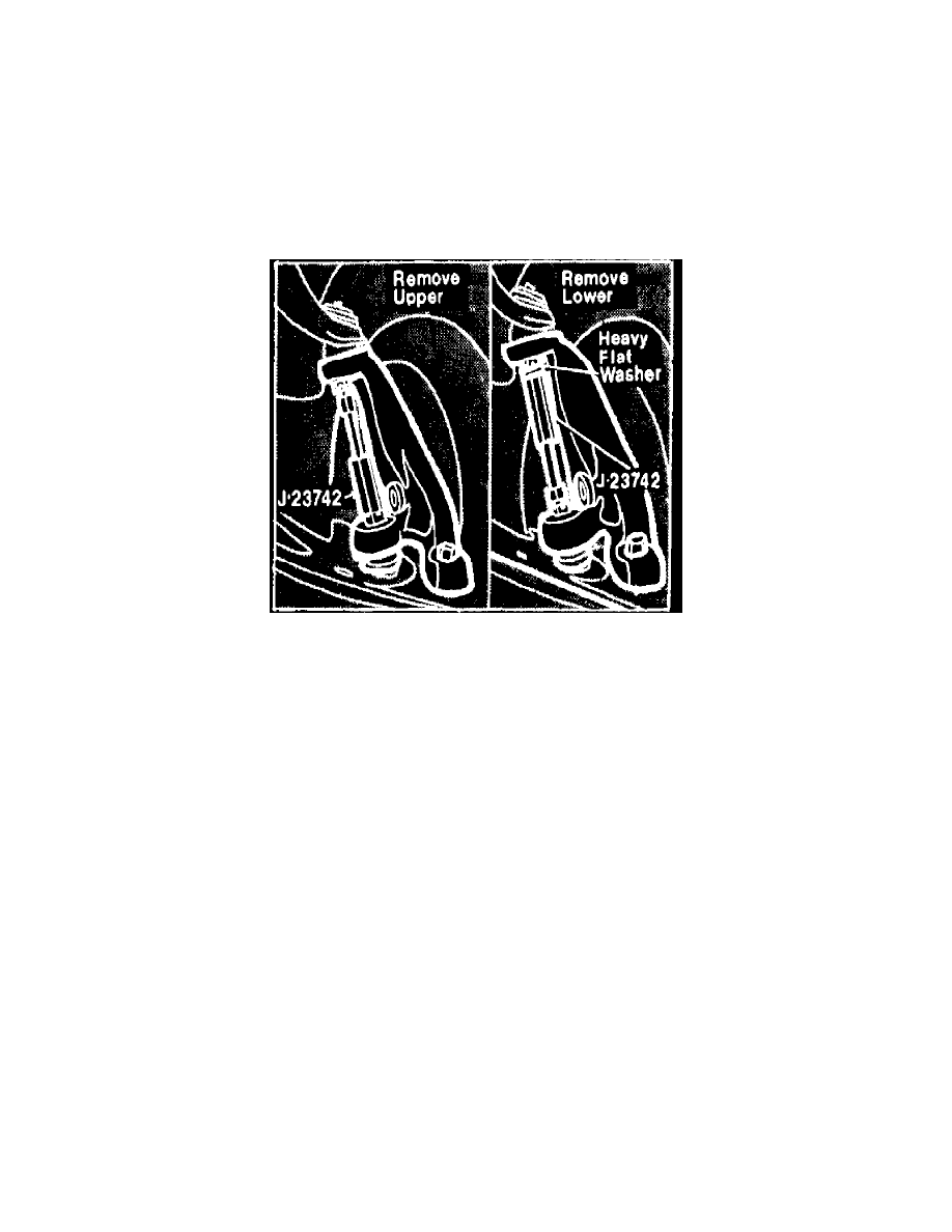
Fig. 3 Removing ball joint stud from steering knuckle
1.
Support vehicle at frame and remove wheel assembly.
2.
Remove cotter pin from upper ball joint stud, loosen nut approximately 2 turns, do not remove nut.
3.
Position tool as shown in Fig. 3, turn threaded end of tool until stud disengages knuckle.
4.
Position jack under lower control arm at spring seat, raise jack until compression is relieved from upper control arm bumper.
5.
Remove stud nut, lift control arm from steering knuckle and place a block of wood between control arm and frame.
6.
On all models:
a. Center punch rivet head as close to center as possible.
b. Using a 1/8 inch twist drill, drill through center of rivet approximately 1/2 rivet length deep.
c. Remove rivet head using a 1/2 inch drill.
d. Using a chisel, remove rivet heads, then drive rivets out using a suitable punch.
7.
Position ball joint on upper control arm. Install bolts through bottom of control arm with nuts on top, torque to 8 ft. lbs.
8.
On all models, position ball joint stud so cotter pin hole is facing forward and remove wooden block from between control arm and frame.
9.
Place wheels in straight ahead position, raise jack under lower control until ball joint stud can be installed in steering knuckle.
10.
Install castellated nut on ball joint stud. Torque nut to 65 ft. lbs. If cotter pin holes do not align, do not loosen nut, however, tighten until
cotter pin can be installed.
11.
Install wheel assembly and lower vehicle.