
Rendezvous FWD V6-3.4L VIN E (2005)
Crankshaft Position Sensor: Testing and Inspection
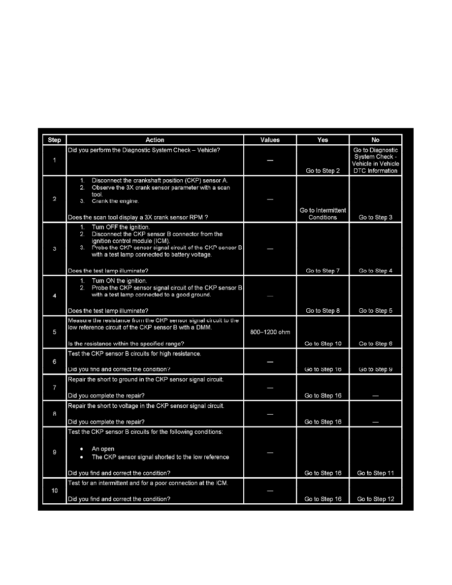
CRANKSHAFT POSITION SENSOR (CKP) SYSTEM DIAGNOSIS
CIRCUIT DESCRIPTION
The crankshaft position (CKP) sensor B is a 7X variable reluctance sensor. This produces 7 digital ON/OFF pulses per engine revolution. These
pulses occur when a reluctor wheel, mounted to the crankshaft and containing 6 slots evenly spaced 60 degrees apart and one slot spaced at 10
degrees, passes by the sensor. The 7X sensor is connected directly to the ignition control module (ICM). The sensor wiring includes 2 circuits, a CKP
senor signal circuit, and a low reference circuit. The ICM uses the 7X signal to determine the engine position and speed. There are no DTCs to
diagnose the CKP sensor B. This CKP sensor system diagnosis is used to diagnose a fault with the CKP sensor B and the CKP sensor B circuits.
TEST
Steps 1-10