
Riviera V6-3.8L VIN K (1996)
Powertrain Control Module: Service and Repair
CAUTIONS:
^
In order to prevent possible electrostatic discharge damage to the PCM, do not touch the connector pins or soldered components on the circuit
board.
^
In order to prevent internal PCM damage, leave the ignition OFF when installing or removing the PCM connectors and disconnecting or
reconnecting the power to the PCM (battery cable, PCM pigtail, PCM fuse, jumper cables, etc.).
NOTES ON REPLACEMENT
Service of the PCM should normally consist of either replacement of the PCM or EEPROM programming. If the diagnostic procedures call for PCM
Replacement, check the PCM first to see if it is the correct part. If the PCM is faulty, remove it and install the new service PCM.
The new service PCM will not be programmed. You must program the new PCM. DTC PO6O2 indicates the EEPROM is not programmed or has
malfunctioned.
When replacing the production PCM with a service PCM (controller), it is important to transfer the broadcast code and production PCM number to
the service PCM label. Do not record on PCM cover. This will allow positive identification of PCM parts throughout the service life of the vehicle.
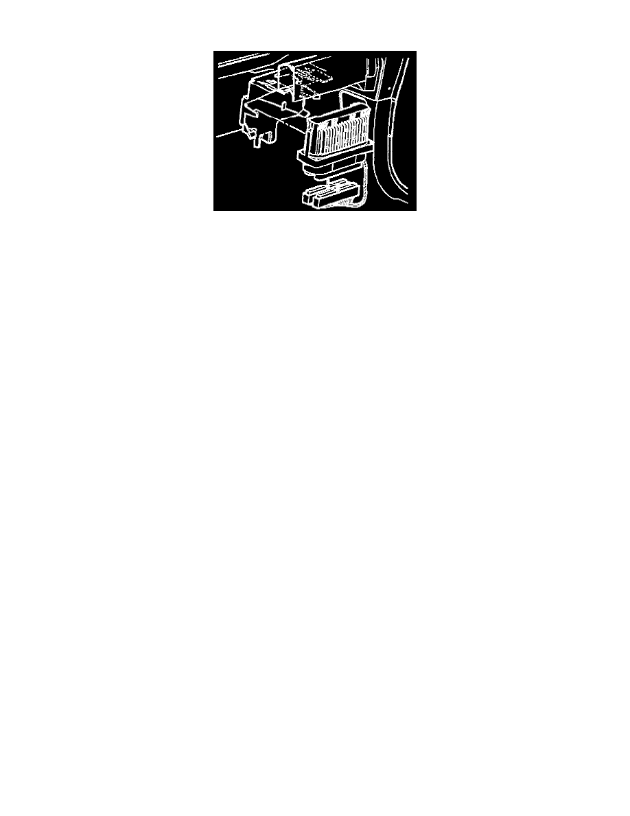
REMOVE OR DISCONNECT
1. Disconnect the negative battery cable. Refer to cautions at the top of this article.
2. Remove the PCM from mounting hardware.
3. Remove the harness connectors from PCM.
4. Remove the PCM from instrument panel.
5. If the PCM is being replaced, remove the KS module for installation in the new PCM.
INSTALL OR CONNECT
1. If a new PCM is being installed, install the KS module from the original PCM.
2. Install the connectors to PCM.
3. Install the PCM into vehicle.
4. Connect the negative battery cable.
5. If a new PCM is being installed, program the EEPROM.
EEPROM PROGRAMMING
1. Set-up - Ensure that the following conditions have been met:
^
The battery is fully charged.
^
The ignition is ON.
^
The Vehicle Interface Module cable connection at the DLC is secure.
2. Program the PCM using the latest software matching the vehicle. Refer to up-to-date Techline equipment users instructions.
3. If the PCM fails to program, proceed as follows:
^
Ensure that all PCM connections are OK.
^
Check the Techline equipment for the latest software version.
^
Attempt to program the PCM. If the PCM still cannot be programmed properly, replace the PCM. You must program the replacement PCM.
FUNCTIONAL CHECK
1. Perform the On-Board Diagnostic System Check. See: Testing and Inspection
2. Start the engine and the engine run for one minute.