Riviera V8-307 5.0L (1982)

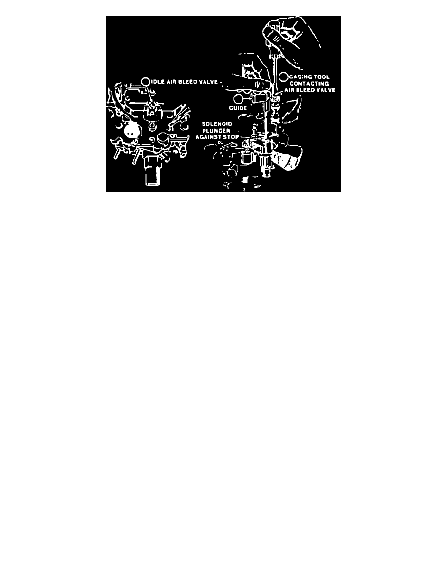
FIGURE 4
Idle Air Bleed Valve
1.
Presetting The Idle Air Bleed Valve
a.
Install Idle Air Bleed Valve Gaging Tool J-33815-2, BT-8253-B, or equivalent, in throttle lever side "D" shaped vent hole in the air horn
casting. The upper end of the tool should be positioned over the open cavity next to the Idle Air Bleed Valve (See Figure 4).
b.
While holding the gaging tool down lightly, so that the solenoid plunger is against the solenoid stop. adjust the Idle Air Bleed Valve so that
the gaging tool will pivot over and just contact the top of the valve. The valve is now preset for on-car adjustment (See Figure 4).
C.
Remove gaging tool.
2.
Adjusting The Idle Air Bleed Valve
a.
Connect dwell meter (or use ALCL Tool) to M/C solenoid dwell terminal (6 cylinder scale).
b.
Start engine and allow it to reach normal operating temperature.
c.
While idling in Drive, use a screwdriver to slowly turn valve counterclockwise or clockwise, until the dwell reading varies within the 35-40~
range, attempting to be as close to 40~ as possible. Perform this step carefully. The Air Bleed Valve is very sensitive and should be turned in
1/8 turn increments only.
d.
If, after perfoming Steps b and c above, the dwell reading is not within the 35-40~ range, it will be necessary to remove the plugs and adjust
the Idle Mixture Needles.
3.
Idle Mixture Needle Plug Removal - ONLY IF NECESSARY:
a.
Remove the carburetor from the engine, following normal service procedures, to gain access to the plugs covering the Idle Mixture Needles.
b.
Invert carburetor and drain fuel into a suitable container.
c.
Place carburetor on a suitable holding fixture, with manifold side up. Use care to avoid damaging linkage, tubes, and parts protruding from
air horn.
d.
Make two parallel cuts in the throttle body, one on each side of the locator points beneath the Idle Mixture Needle Plug (manifold side), with
a hacksaw. The cuts should reach down to the steel plug, but should not extend more than 1/8" beyond the locator points. The distance
between the saw cuts depends on the size of the punch to be used.
e.
Place a flat punch near the ends of the saw marks in the throttle body. Hold the punch at a 45~ angle and drive it into the throttle body until
the casting breaks away, exposing the plug.
The hardened plug will break, rather than remain intact. It is not necessary to remove the plug in one piece, but remove the loose pieces.
