
Riviera V8-307 5.0L (1982)
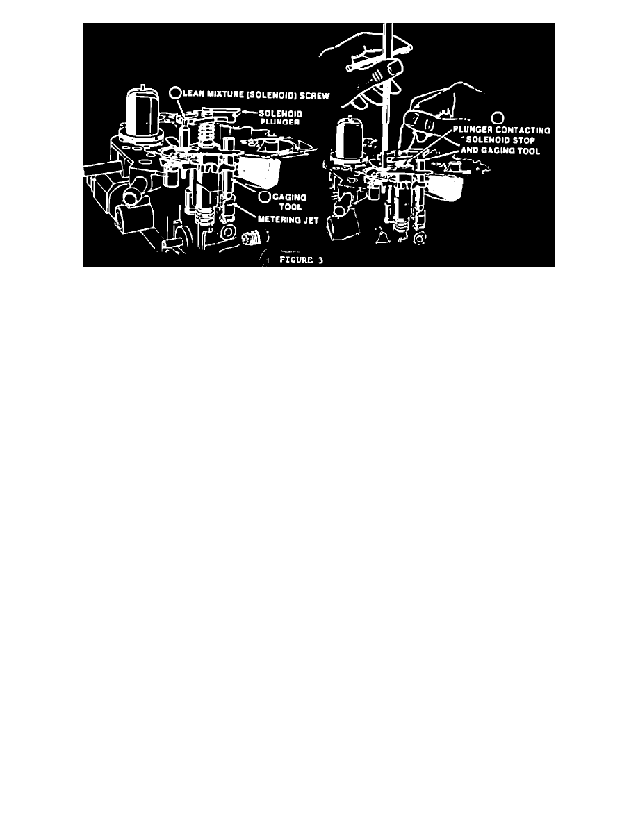
FIGURE 3
1.
Remove air horn, mixture control solenoid plunger, air horn gasket, plastic filler block, using normal service procedures.
2.
Remove Throttle lever side metering rod. Install Mixture Control Solenoid Gaging Tool J-33815-1, BT-8253-A, or equivalent, over the throttle
lever side metering Jet rod guide, and temporarily reinstall the solenoid plunger into the solenoid body (See Figure 3).
3.
Holding the solenoid plunger in the DOWN position, use Tool J-28696-10, BT-7928, or equivalent, to turn lean mixture (solenoid) screw
counterclockwise until the plunger breaks contact with the gaging tool. The adjustment is correct when the solenoid plunger is contacting BOTH
the SOLENOID STOP and the GAGING TOOL (See Figure 3).
4.
Remove solenoid plunger and gaging tool, and reinstall Metering Rod and plastic filler block. Invert air horn, and remove rich mixture stop screw
from bottom side of air horn, using Tool J-28696-4, BT-7967A or equivalent.
5.
Remove lean mixture screw plug and the rich mixture stop screw plug from air horn, using a suitably sized punch. Refer to Page 6C1-10 and
6C1-11 in the 1982 Chassis Service Manual.
6.
Reinstall rich mixture stop screw in air horn and bottom lightly, then back screw out 1/4 turn.
7.
Remove Idle Air Bleed Cover.
8.
Reinstall air horn gasket, mixture control solenoid plunger and air horn to carburetor. Insert External Float Gage J-9789-130, BT-7720 in vent
hole and, with Tool J-28696-10, BT-7928, or equivalent, adjust rich mixture stop screw to obtain 4/32" total plunger travel.
9.
With solenoid plunger travel correctly set, install Plugs (supplied in service kits) in the air horn, as follows:
a.
Install plug, hollow end down, into the access hole to lean mixture (solenoid) screws, and use suitably sized punch to drive plug into the air
horn until the top of the plug is even with the lower edge of the hole chamfer. Plug must be installed to retain the screw setting and to prevent
fuel vapor loss.
b.
Install plug, with hollow end down, over the rich mixture stop screw access hole, and drive plug into place so that the top of the plug is 1/16"
below the surface of the air horn casting. Plug must be installed to retain screw setting.