
Roadmaster V8-305 5.0L (1992)
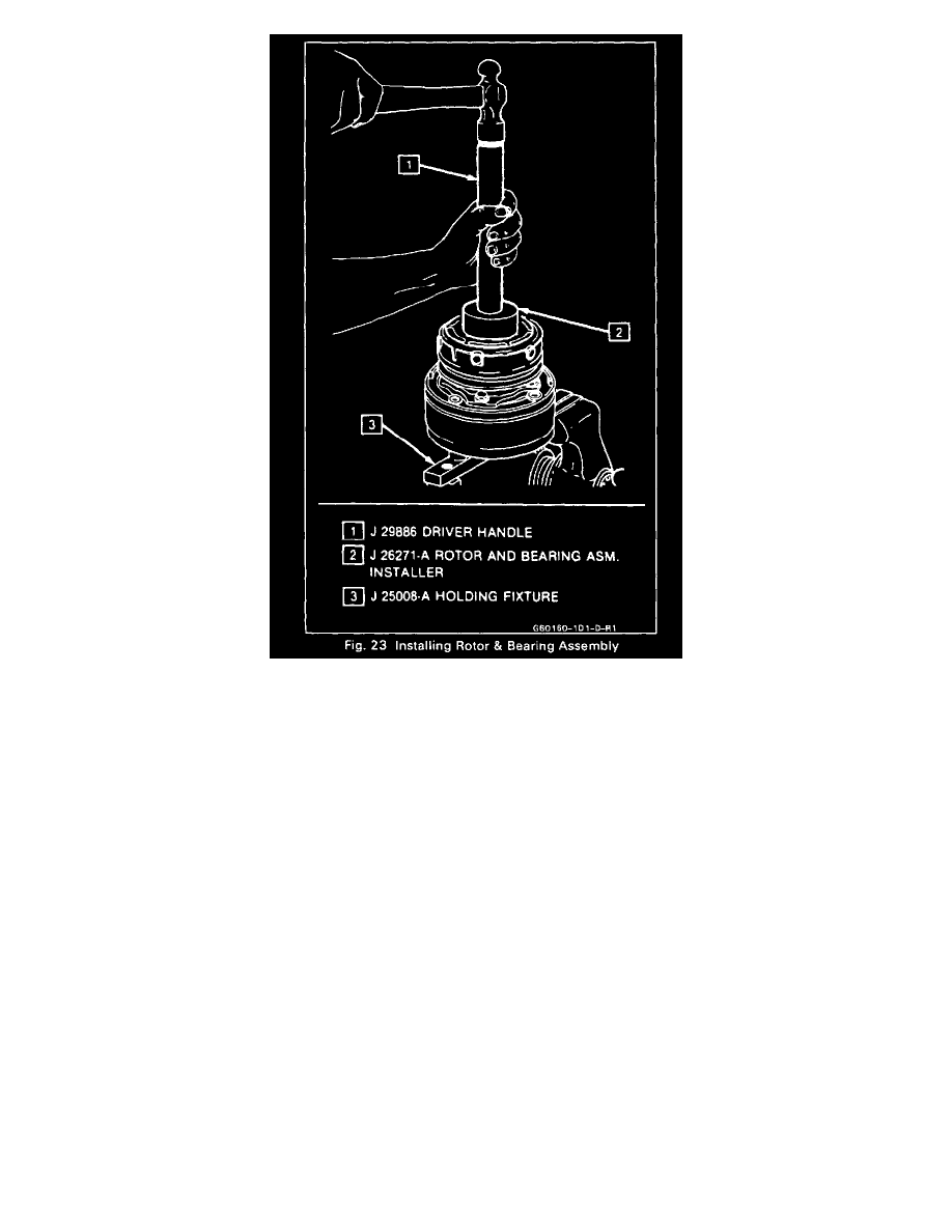
Reassemble the Rotor and Bearing assembly to the front head of the compressor using Rotor & Bearing Installer J 26271-A. With Installer
assembled to the Universal Handle 329886, as shown in Figure 23, force will be applied to the inner race of the bearing and the face of the rotor
when installing the assembly onto the front head of the compressor.
5. Install rotor and bearing assembly retainer ring, using Snap Ring Pliers J 6083 (Fig. 9).
6. Apply sealer include GM equivalent (Loctite RC-75, Loctite 601 or equivalent) to threads of pulley rim mounting screws. Install screws but do not
torque the screws.
7. Rotate the pulley rim and rotor to insure that pulley rim is rotating "in-line". If pulley rim is distorted (does not rotate in-line), adjust or replace
pulley rim.
8. Tighten pulley rim mounting screws to 11 N.m (100 in.lbs.) torque and lock screw heads in place by bending screw head washer similar to
original crimp.
9. Reinstall Clutch Plate and Hub assembly.
6 Pole Clutch
6 POLE CLUTCH
Remove or Disconnect
1. Remove the clutch plate and hub assembly as described previously.