
Roadmaster V8-305 5.0L (1992)
Electronic Brake Control Module: Diagnostic Aids
Troubleshooting Tests
PROBING
After probing, when reconnecting connectors or replacing terminals, always be sure to reinstall Connector Position Assurance (CPA) and Terminal
Position Assurance (TPA).
Frontprobe
When frontprobing of connectors is required, always use a mating terminal adapter (GM Connector Test Adapter Kit J 35616 or equivalent). The
use of proper adaptors will ensure that proper terminal contact integrity is maintained.
Backprobe
Only backprobe connector terminals when specifically called for in diagnostic procedures. Since backprobing can be a source of damage to
connector terminals, extra care must be taken to avoid deforming the terminal, either by forcing the test probe too far into the cavity or by using
too large a test probe.
After backprobing any connector, always check for terminal damage. If terminal damage is suspected, check for proper terminal contact, see
CHECKING TERMINAL CONTACT.
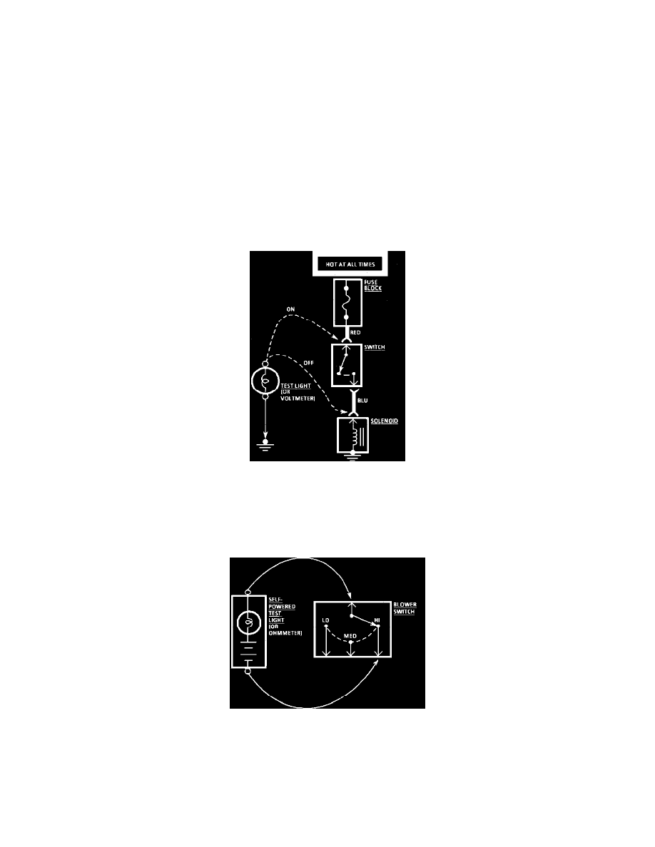
Voltage Check
TESTING FOR VOLTAGE
1. Connect one lead of a test light to a known good ground. When using a voltmeter, be sure the voltmeter's negative lead is connected to ground.
2. Connect the other lead of the test light or voltmeter to a selected test point (connector or terminal).
3. If the test light illuminates, there is voltage present. When using a voltmeter, note the voltage reading.
Continuity Check through a Switch
TESTING FOR CONTINUITY
1. Remove the fuse to the circuit involved.
2. Connect one lead of a self-powered test light or ohmmeter to one end of the part of the circuit you wish to test.
3. Connect the other lead to the other end of the circuit.
4. If the self-powered test light glows, there is continuity. When using an ohmmeter, low or no resistance means good continuity.