
Roadmaster V8-305 5.0L (1992)
Ignition Control Module: Description and Operation
Ignition Module Operation
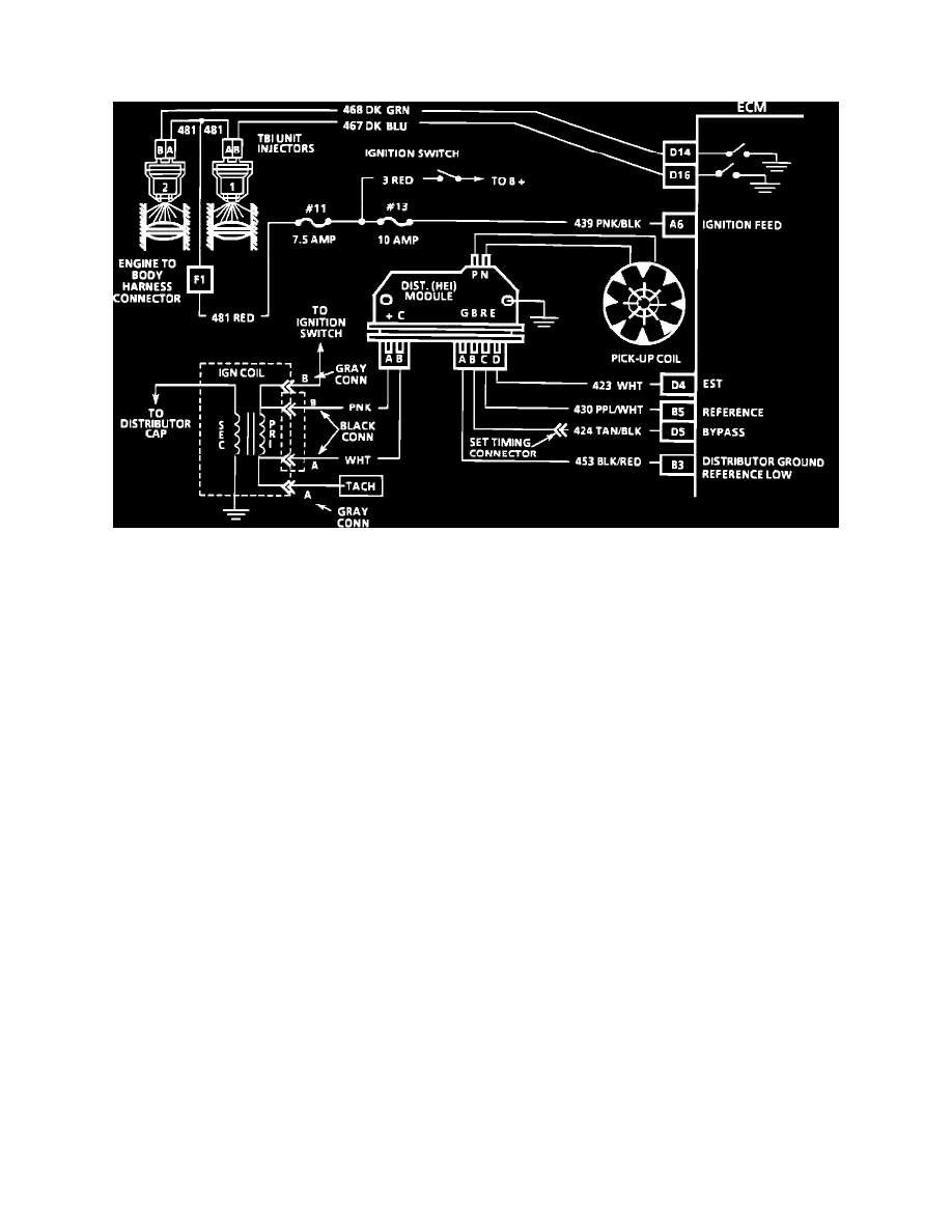
Wiring Diagram For Engine No Start
The Electronic Spark Timing (EST) system consists of an HEI module, Electronic Control Module (ECM), and connecting wires. The distributor has
four wires that connect the HEI module to the ECM. These circuits perform the following functions.
1.
Circuit 430 is the distributor reference. This provides the ECM with rpm and crankshaft position information. If the wire becomes open or
grounded the engine will not run because the ECM will not operate the injectors. If the engine cranks but will not run See Chart A-3.
2.
Circuit 453 is the reference ground. This wire is grounded in the distributor and makes sure the ground circuit has no voltage drop which could
affect performance. If it is open, it may cause poor performance.
3.
Circuit 424 is the bypass circuit. At about 400 rpm the ECM applies 5.0 volts to this circuit to switch spark timing control from the HEI module to
the ECM. The wire goes through a connector between the 4-wire connector and the ECM. This is disconnected to set the base timing. An open or
grounded bypass circuit will set a Code 42 and the engine will run at base timing, plus a small amount of advance controlled by the HEI module.
4.
Circuit 423 triggers the HEI module. The ECM does not know what the actual timing is, but it does know when it gets the reference signal. It then
advances or retards the spark form that point. Therefore, if the base timing is set incorrectly, the entire spark curve will be incorrect. An open or
ground, in the EST circuit, will set a Code 42 and cause the engine to run on the HEI module timing. This will cause poor performance and poor
fuel economy.