
Roadmaster V8-305 5.0L (1992)
Steering Wheel: All Technical Service Bulletins
Charts: 1 Thru 6 Usage
All Charts
Before replacing any SWC components, check for poor connections or bent terminals.
Chart 1 - SWC Head Illumination does not come on with Park lights or Headlights
The Turn Signal Switch (TSS) illumination wire should be checked by measuring the voltage to ground at the TSS illumination spring loaded brush. If
11 or more volts are not present; replace the TSS. If 11 or more volts are present, perform Cancel Cam checks as listed. If OK, replace the Cancel Cam.
Chart 2 - Only some functions operate from the Steering Wheel Controls but all functions operate from the Radio Controls
Spelling Typo in box on the left hand side - Check for an open circuit in the E&C data line or for poor connections at the HVAC Control Head.
Chart 3 - None of the functions operate from the Steering Wheel Controls but all functions operate from the Radio Controls
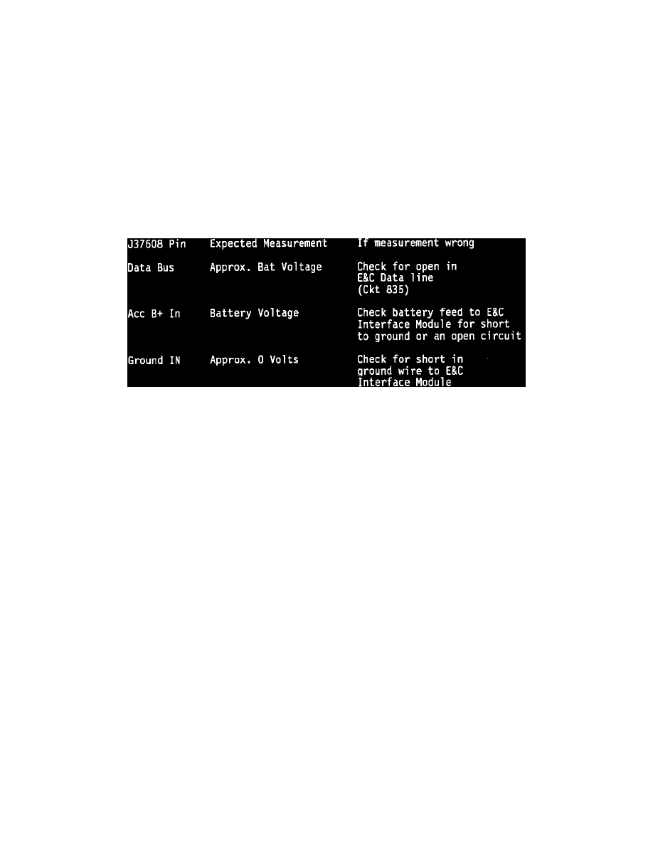
There are two boxes that instruct you to "Replace the E&C Interface Module". Before replacing the module, check the battery, ground, and E&C data
circuits that connect to the module. Ignition switch "OFF". Remove the jumper harnesses from J37608. Connect the Radio Interface Module portion of
the Turn Signal Switch harness to J37608. With the Ignition Switch in Run, make the voltage measurements at the E&C Interface half of J37608:
With the Ignition Switch Off, measure the resistance between the Ground In terminal of J37608 and a known good ground. If resistance is more than 0.5
ohms, repair high resistance in ground wire to E&C Interface module. If OK, replace the E&C Interface Module.
Chart 6 - None of the functions operate from both the Steering Wheel Controls and the Radio Controls or none of the functions operate from the Steering
Wheel Controls and only some functions operate from the Radio Controls
For the boxes "Replace the E&C Interface Module", before replacing the module - perform the same E&C Interface Module Power, Ground, and E&C
data line checks as instructed above for chart 3.
Turn Signal Switch/Cancel Cam Optical Test
Before performing the optical test, verify that battery voltage is present at the spring loaded brush in the turn signal switch. If not, replace the turn signal
switch. Verify the ground spring loaded brush in the turn signal switch, that there is not an open circuit or shorted wire. Repair as needed. Refer to the
vehicle service manual to determine the respective brushes.