
Roadmaster V8-350 5.7L (1994)
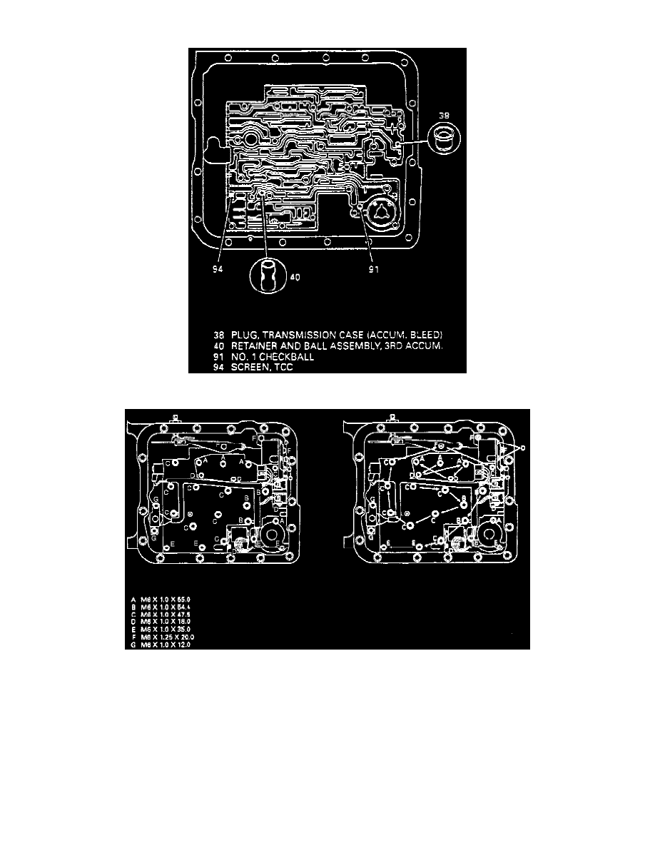
Fig.11 Control Valve Body Check Ball Locations
Fig.12 Transmission Case Check Ball Locations
Fig.13 Control Valve Body Bolts And Tightening Pattern
1. Raise and support vehicle.
2. Remove oil pan and gasket
3. Remove oil filter and filter seal.
4. Disconnect electrical connectors from control valve body components.
5. Remove TCC solenoid bolts and solenoid assembly with O-ring seal.
6. Remove wiring harness retaining bolts, then set harness aside, Fig. 10.
7. Remove manual detent spring assembly attaching bolt.
8. Remove remaining control valve body attaching bolts.
9. Remove manual valve link, then the control valve body.
10. Reverse procedure to install, noting the following:
a. Before installing valve body, ensure valve body and transmission case check balls are in their correct location. Refer to Fig. 11 and Fig. 12 for