
Roadmaster Estate Wagon V8-305 5.0L (1991)
Transmission Position Switch/Sensor: Testing and Inspection
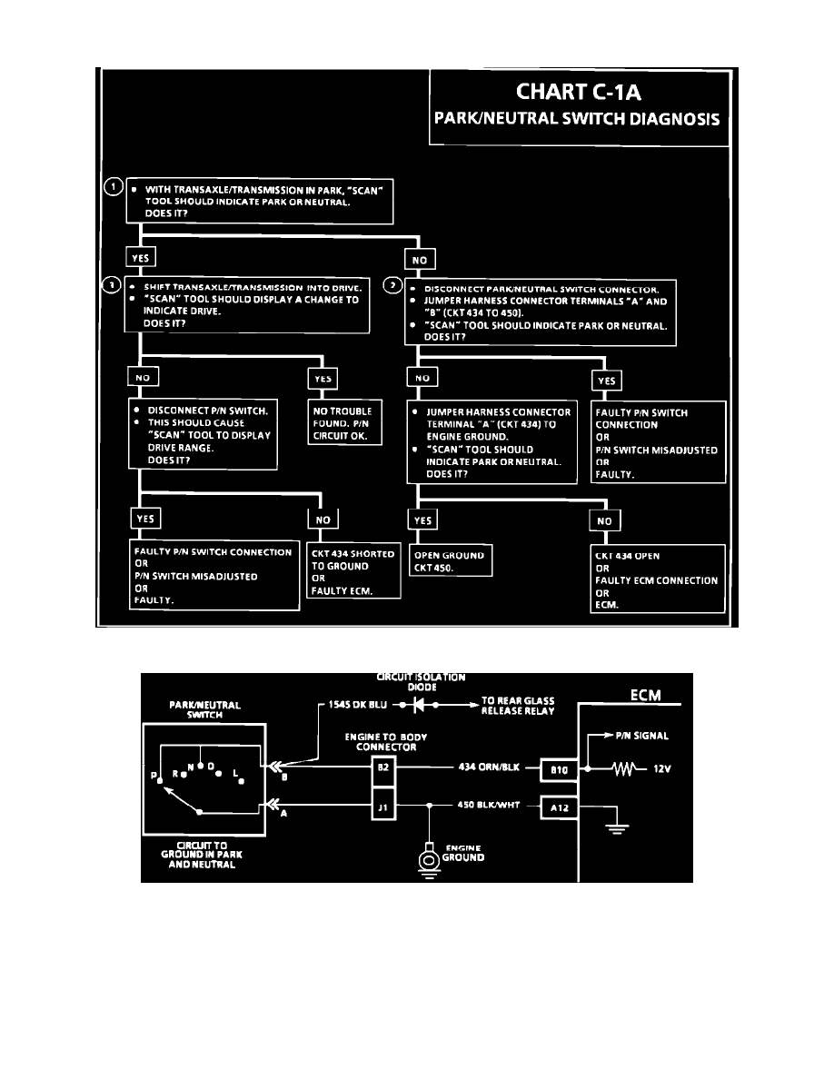
Chart C-1A
Wiring Diagram For P/N Switch
CIRCUIT DESCRIPTION:
The PARK/NEUTRAL switch contacts are closed to ground in park or neutral and open in drive ranges. The ECM supplies ignition voltage through a
current limiting resistor to circuit 434, and senses a closed switch when the voltage on circuit 434 drops to less than one volt. The ECM uses the P/N
signal as one of the inputs to control idle air, vehicle speed sensor diagnostics, and exhaust gas recirculation. If circuit 434 indicates a grounded P/N
switch, while in the drive range, the EGR would be inoperative and engine detonation may result. If circuit 434 always indicates drive (open), a drop in
idle speed may exist when the gear selector is moved into the drive range.