
Roadmaster Estate Wagon V8-350 5.7L (1993)
Wiring Diagram
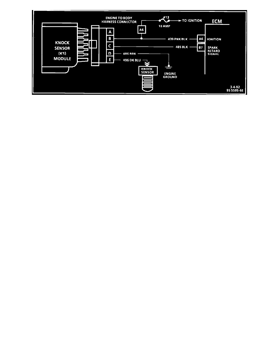
CIRCUIT DESCRIPTION:
Knock sensor (KS) control is accomplished with a module that sends a voltage (8 to 10 volts) to the ECM. As the sensor detects engine knock, the
voltage from the KS module to the ECM is shut "OFF" and this signals the ECM to retard the timing, if engine speed is over approximately 900 rpm.
TEST DESCRIPTION: The numbers below refer to circled numbers on the diagnostic chart.
1.
If a DTC 43 is not set, but a knock signal is indicated while running at 1500 rpm, listen for an internal engine noise. Under a no load condition,
there should not be any detonation, and if a knock is noticed, an internal engine problem may exist.
2.
Usually a knock signal can be generated by tapping on right exhaust manifold. This test can also be performed at idle. Test number one was run at
1500 rpm, to determine if a constant knock signal was present, which would affect engine performance.
3.
This tests whether the knock signal is due to the knock sensor, a basic engine problem, or the KS module.
4.
If the KS module ground circuit is faulty, the KS module will not function correctly. The test light should illuminate indicating the ground circuit
is OK.
5.
Contacting circuit 496, with a test light to 12 volts, should generate a knock signal to determine whether the knock sensor is faulty, or the KS
module can not recognize a knock signal.
DIAGNOSTIC AIDS:
A Scan tool can be used to monitor the KS system. The Knock signal can be monitored to see if the knock sensor is detecting a knock condition, and if
the KS module is functioning. The knock signal should display "YES" whenever an engine detonation is present. If the KS system checks OK, but
detonation is the complaint, refer to Diagnosis By Symptom See: Testing and Inspection