
Skyhawk L4-121 2.0L VIN P TBI (1984)
Vacuum Pump: Description and Operation
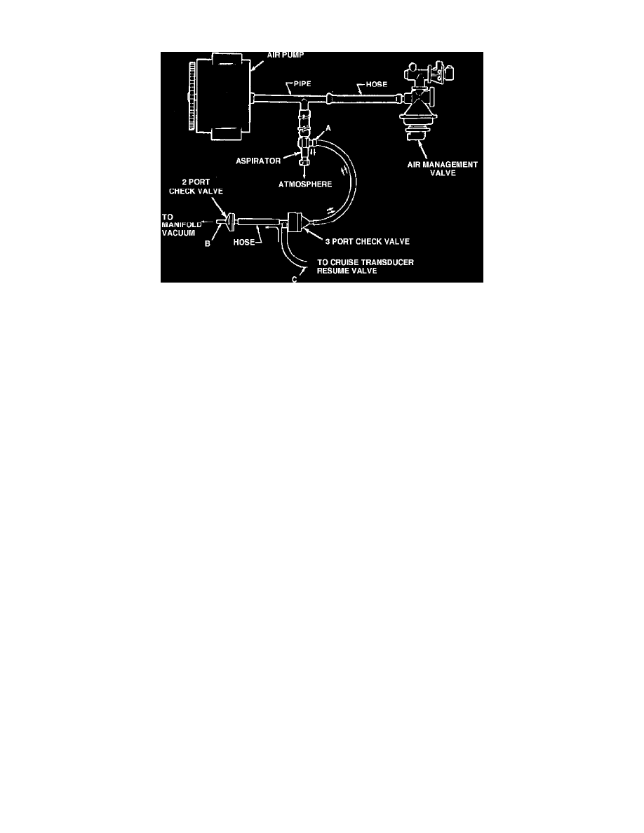
Fig. 11 Aspirated assisted vacuum system schematic
The aspirator assisted vacuum system supplements engine vacuum when engine vacuum is low. The system, Fig. 11, consists of an aspirator, 3-Port
check valve, 2-Port check valve and related components such as the air pump and air management valve. The air for the aspirator is tapped off the air
line that connects the air pump to the air management valve. Aspirator vacuum and manifold vacuum (after passing through the 2-Port check valve)
supply the two upper ports of the 3-Port check valve. The lower of the 3-port check valve supplies air to the cruise control transducer. The aspirator
assisted vacuum system operates as follows:
1.
Under normal vacuum conditions, air is bled into the system from the transducer resume valve to the lower ``T'' of the 3-port check valve, then to
the 2-Port check valve and finally into the intake manifold, Fig. 11.
2.
Also during normal operation, as the air pump is pumping air into the air management valve, a small amount of air is diverted through the aspirator
to the atmosphere. As air passes through the aspirator, a venturi action inside the aspirator assembly develops a vacuum. This vacuum is used to
provide the vacuum assist needed under high cruise conditions.
3.
Should manifold vacuum fall below aspirator vacuum, the 2-port check valve is designed to close while the 3-port check valve is designed to open.
Opening of the 3-port check valve exposes the higher vacuum at the aspirator, providing the needed vacuum for proper cruise operation. To
check the aspirator system for correct operation, note the following information:
1.
Ensure all hoses and connections are secure and check valves are correctly installed. The check valves are arrowhead shaped in the direction
of air flow.
2.
Connect a suitable vacuum gauge to the aspirator output at point A, Fig. 11.
3.
Start and operate engine at 2500 RPM. Engine should be thoroughly warmed up to ensure that the computer command control system
(CCC) is operating in closed loop.
4.
Check vacuum gauge. A minimum of 6 inches should be indicated. If vacuum reading is not within specified amount, clean aspirator using a
suitable solvent and recheck. Also check air pump for air output. If there is no air output from the air pump, check air pump for damage. If air
pump is not damaged, proceed to step a.
a. Disconnect vacuum gauge at port A, Fig. 11. Disconnect and plug 2-port check valve at port B. Blow air into the resume valve hose at port C.
Air should flow through and exit at port A.
b. Remove plug from 2-port check valve at port B and plug hose at port A. Blow air into cruise resume valve at port C. Air should flow and exit
at port B. Steps a & b determine if the hoses and check valves are operating in one direction. To check for operation in the opposite
direction, proceed to step c.
c. Blow air into hose at port A while port B is plugged, then into port B while hose at port A is plugged. No air should exist at port C in either
case.