
Skylark L4-138 2.3L DOHC VIN D MFI QUAD 4 (1989)
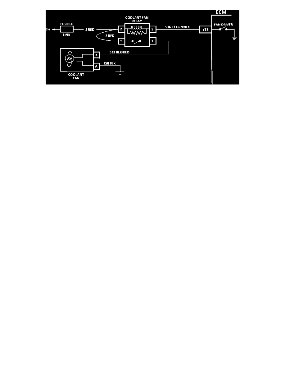
Chart C-12 Wiring Diagram
CIRCUIT DESCRIPTION:
The electric coolant fan is controlled by the ECM through the fan relay based on inputs from the coolant temperature sensor, manifold air temperature,
the A/C control switch, A/C pressure sensor and the vehicle speed sensor. The ECM controls the coolant fan by grounding CKT 536 which turns "ON"
fan relay. The fan relay will be turned "ON" when any one of the following conditions exist:
^
Coolant temperature 103~C - 106~C or more.
^
A/C clutch requested and vehicle speed is less than 35 mph.
^
The fan relay will engage regardless of vehicle speed if:
^
Code 14 or 15 are set.
^
Coolant temperature 115~C - 118~C or more.
^
A/C pressure is high.
TEST DESCRIPTION:Numbers below refer to circled numbers on the diagnostic chart.
1.
With the diagnostic terminal grounded, the coolant fan control drivers will close, which should energize the fan control relay.
2.
Test to see if fault is in wiring to the fan or the fan connection.
DIAGNOSTIC AIDS:
^
If the owner complained of an overheating problem it must be determined if the complaint was due to an actual boil over, or the "hot light,"
or temperature gauge indicated overheating.
^
If the gauge, or light, indicates overheating, but no boil over is detected, the gauge or light circuit should be checked, The gauge accuracy can
also be checked by comparing the coolant sensor reading using a "Scan" tool with the reading of the gauge.
^
If the engine is actually overheating, and the gauge indicates overheating, but the coolant fan is not coming "ON", the coolant sensor has
probably shifted out of calibration and should be replaced.
^
If the engine is overheating, and the coolant fan is "ON", the cooling system should be checked.
System Diagnosis
Coolant Fan Does Not Turn On
1.
Turn ignition switch to RUN position, ground terminal B white wire of the ALDL connector.
2.
If coolant fan runs, problem is ECM related.
3.
If coolant fan does not run, ground terminal C3/F7 light green/black wire of the ECM with a fused jumper.
4.
If coolant fan runs, problem is ECM related.
5.
If coolant fan does not run, leaving terminal C3/F7 grounded, disconnect coolant fan relay connector.
6.
Measure voltage from terminal 2 red wire of the coolant fan relay connector and ground.
7.
If zero voltage is indicated, check red wire and fusible link F for an open circuit.
8.
If battery voltage is indicated, measure voltage between terminals 2 red wire and 5 light green/black wire of the coolant fan relay connector.
9.
If zero voltage is indicated, check light green/black wire for an open circuit.
10.
If battery voltage is indicated, measure voltage from terminal 1 red wire of the coolant fan relay connector to ground.