
Skylark L4-138 2.3L DOHC VIN D MFI QUAD 4 (1989)
Idle Speed/Throttle Actuator - Electronic: Service and Repair
Idle Air Control (IAC) Valve Replacement
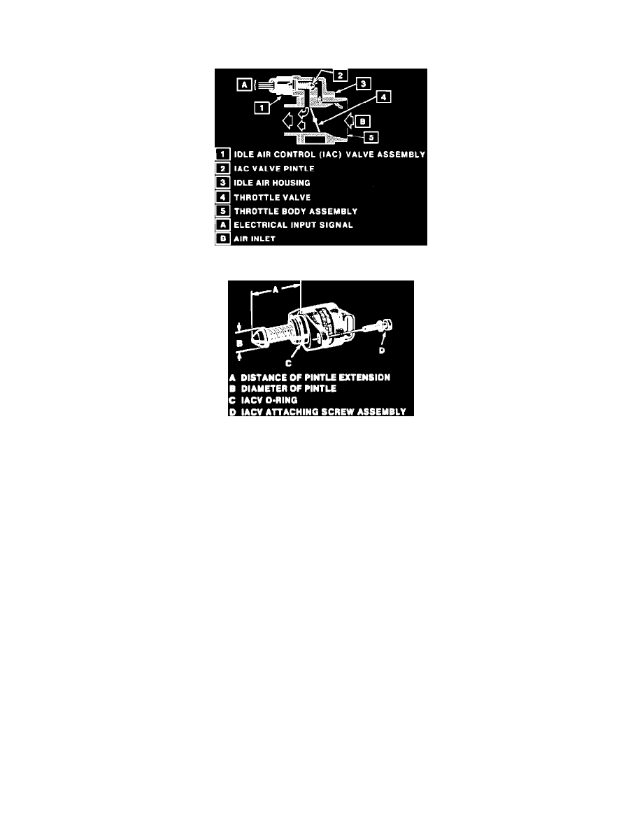
IAC Valve Air Flow Diagram
Idle Air Control (IAC) Valve
REMOVAL:
1.
Remove the idle air control valve electrical connector.
2.
Remove the idle air control valve retaining screws.
3.
Remove the idle air control valve assembly.
NOTE: On idle air control valves that have been in service:
a.
DO NOT push or pull on the idle air control valve pintle. The force required to move the pintle may damage the threads on the worm drive.
b.
DO NOT soak the IAC valve in any liquid cleaner or solvent, damage may result.
c.
Clean the IAC valve "O" ring surface, pintle valve seat and air passage.
d.
Use carburetor cleaner and a parts cleaning brush to remove carbon deposits. DO NOT use a cleaner that contains methyl ethyl ketone. It is
an extremely strong solvent, and not necessary for this type of deposit.
e.
Shiny spots on the pintle or seat are normal, and do not indicate misalignment or a bent pintle shaft.
f.
If the air passage has heavy deposits, remove the throttle body for complete cleaning.
g.
Inspect the IAC valve "O" ring for cuts, cracks, or distortion. Replace if damaged.
h.
If installing a new IAC valve, be sure to replace it with an identical part. IAC valve pintle shape and diameter are designed for the specific
application.
i.
Measure the distance between the tip of the IAC valve pintle and the mounting flange.
j.
If greater than 28mm, use finger pressure to slowly retract the pintle. The force required to retract the pintle of a new valve will not cause
damage to the new valve.
INSTALLATION:
1.
Lubricate the IAC valve "O" ring with clean engine oil.
2.
Install the IAC valve assembly.
3.
Insert the IAC retaining screws and tighten to 3.0 Nm (27 lb.in).
4.
Reconnect the IAC electrical connector.
5.
START the engine to reach normal operating temperature.