
Skylark L4-138 2.3L DOHC VIN D MFI QUAD 4 (1989)
Crankshaft Position Sensor: Description and Operation
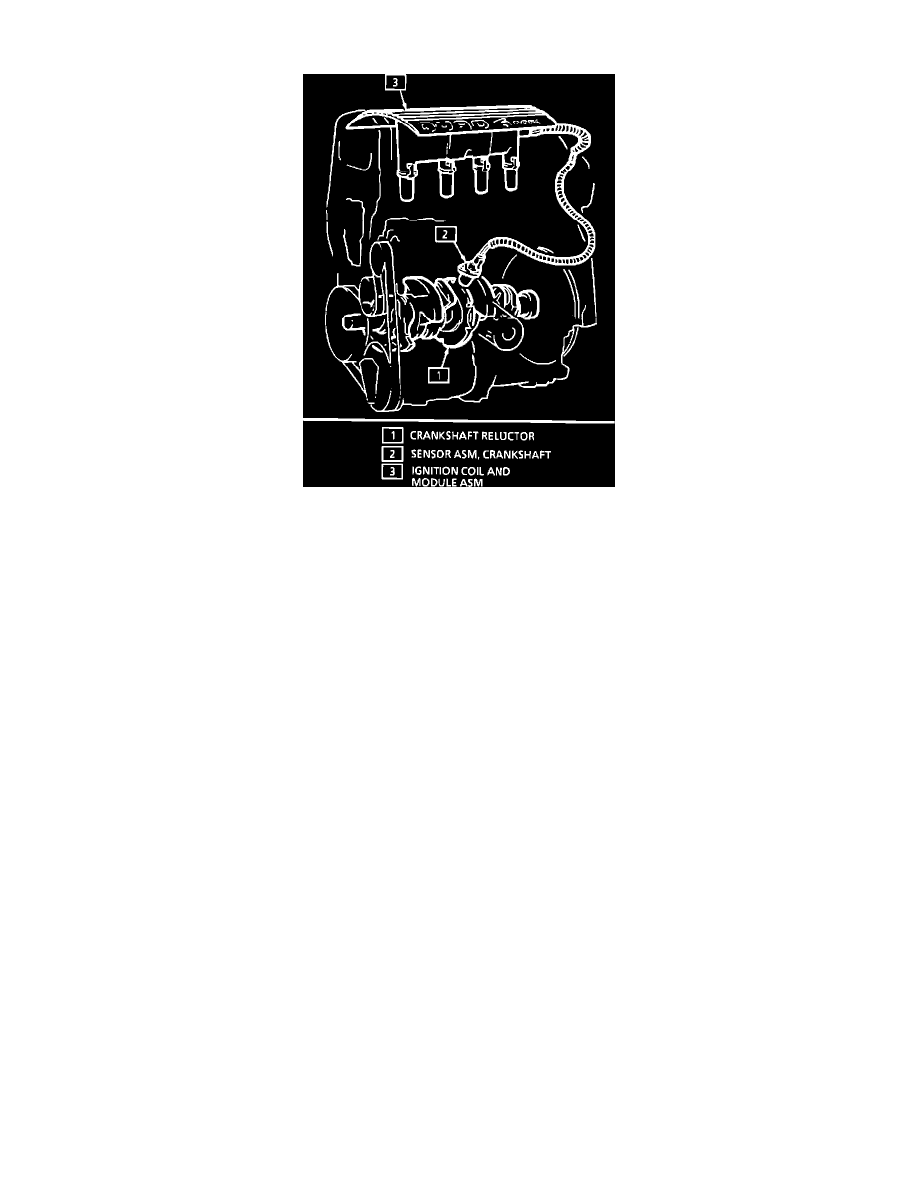
Crankshaft Sensor IDI
This crankshaft sensor is mounted remotely from the module. This sensor protrudes into the block, within approximately 0.050" of the engine crankshaft
reluctor. The reluctor is a special wheel cast into the crankshaft with seven slots cast into it, six of which are evenly spaced 60° apart. A seventh slot is
spaced 10° from one of the other slots and serves to generate a "sync pulse." As the reluctor rotates as part of the crankshaft, the slots change the
magnetic field of the sensor, creating an induced voltage pulse.
Based on the crank sensor pulses, the ignition module sends 2X reference signals to the ECM which are used to indicate crankshaft position and engine
speed. The ignition module continues to send these reference pulses at a rate of one per each 180° of crankshaft rotation. This signal is called the 2X
reference because it occurs 2 times per crankshaft revolution.
The ignition also sends a second, 1X reference signal to the ECM which occurs at the same time as the "sync pulse" from the crankshaft sensor. This
signal is called the 1X reference because it occurs 1 time per crankshaft revolution. The 1X reference and the 2X reference signals are necessary for the
ECM to determine when to activate the fuel injectors.
By comparing the time between pulses, the ignition module can recognize the pulse representing the seventh slot or "sync pulse" which starts the
calculation of the ignition coil sequencing. The second crank pulse following the "sync pulse" signals the ignition module to fire the #2-3 ignition coil,
and the fifth crank pulse signals the ignition module to fire the #1-4 ignition coil.