
Skylark L4-138 2.3L SOHC VIN 3 MFI QUAD 4 (1992)
Idle Speed/Throttle Actuator - Electronic: Description and Operation
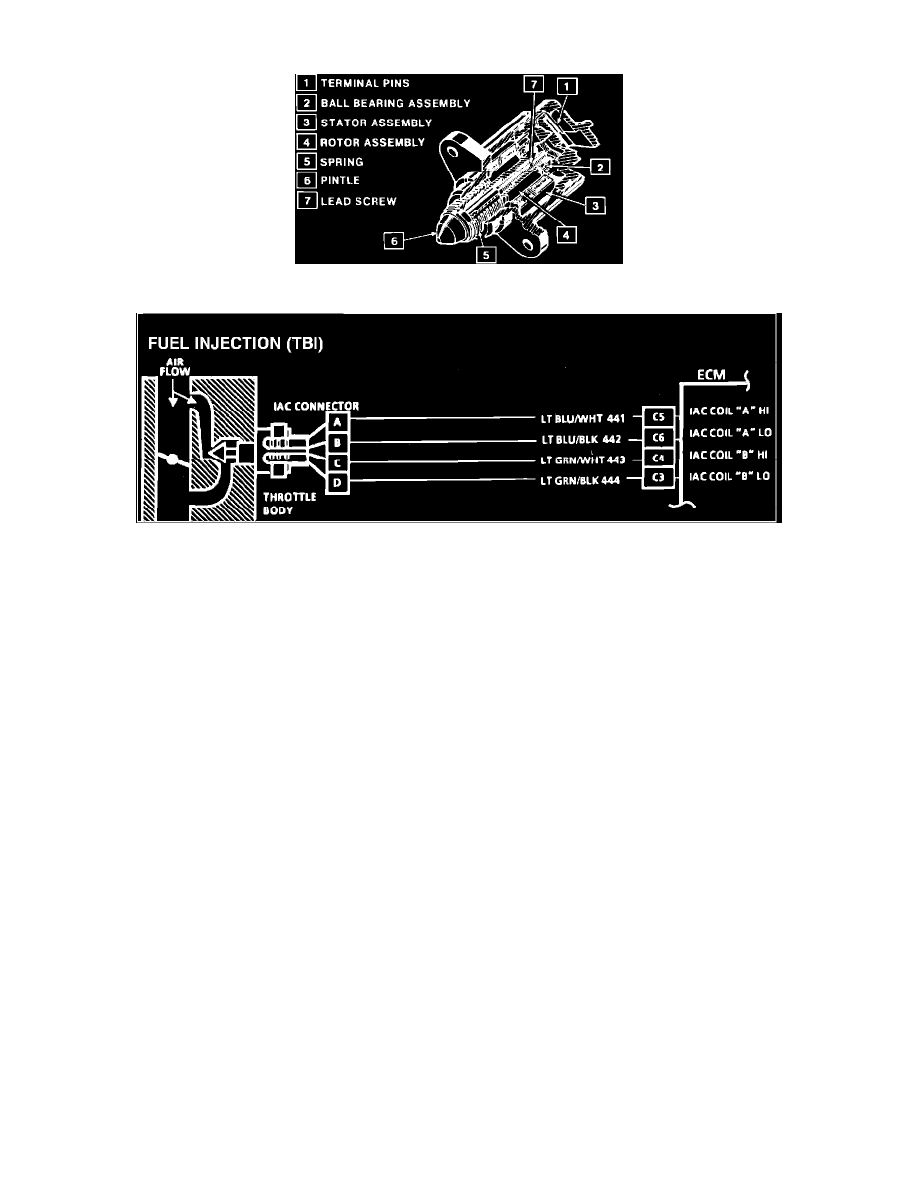
Idle Air Control Valve Assembly (IAC)
Fig. 040 - Wiring Diagram for Chart C-2C Idle Air Control.
NOTE: Because different models and engine applications vary in wire colors, circuit numbers, and pin numbers, the above image is a typical example.
Refer to COMPUTERS AND CONTROL SYSTEMS/SCHEMATIC AND ROUTING DIAGRAMS for specific schematic applications.
PURPOSE
To control the engine idle speed and prevent stalling due to changes in engine load.
OPERATION
The IAC valve controls the amount of air bypassed around the throttle plate. This is actually a controlled vacuum leak. If more air is bypassed, idle
speed will increase, and if less air is bypassed, the idle speed will decrease. The IAC valve accomplishes this by moving a conical shaped pintle in
to decrease bypassed air and out to increase bypassed air. This can be seen as counts as displayed on a "Scan" tool. Inward Movement of the pintle
= Decreased RPM = Lower Counts. Outward Movement of the pintle = Increased RPM = Higher Counts. The ECM uses sensor and switch inputs
to control the position of the IAC pintle. If the pintle is stuck open, the idle speed will remain high. If the pintle is stuck closed, the idle speed will
be too low, and stalling may occur. If the pintle is stuck partially open, the idle speed will be higher than normal, and there will be no response to
changes in engine load such as A/C ("ON") or transmission in ("Drive").
LOCATION
Throttle body.