
Skylark V6-173 2.8L VIN W FI (1985)
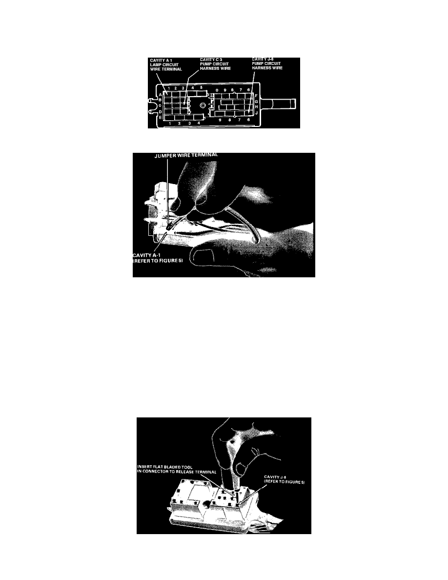
FIGURE 4 - LAMP CIRCUIT JUMPER WIRE INSTALLATION
8.
Using furnished splice clip, splice the furnished jumper wire lead to the two ends of the cut wire. Use rosin core solder and solder this connection.
Refer to Figure 4, View A.
FIGURE 5 - I.P. HARNESS CONNECTOR CAVITY IDENTIFICATION
FIGURE 6 - INSTALLING LAMP CIRCUIT JUMPER WIRE IN I.P. CONNECTOR
9.
Insulate the soldered connection with electrical tape.
10.
Plug the terminal end of the jumper wire into cavity A-1 of the I.P. harness connector. Refer to Figure 5 and Figure 6.
11.
Replace the conduit over the pressure switch branch and main I.P. harness, including the new installed jumper wire. Tape all wires exposed by the
removal of the tape in steps 5 and 6.
12.
Determine if "pump circuit kit" is to be installed in vehicle.. Refer to "Vehicles Involved" and "Parts Information" section of this bulletin.
a.
IF "PUMP CIRCUIT" KIT IS NOT TO BE INSTALLED, STEPS 13 THROUGH 16 ARE NOT REQUIRED, PROCEED TO STEP 17.
b.
IF PUMP CIRCUIT KIT IS TO BE INSTALLED, PROCEED WITH ALL OF THE FOLLOWING STEPS OF THIS PROCEDURE.
13.
Remove the terminal secondary lock from other side of I.P. harness connector. Refer to Figure 2.
FIGURE 7 - UNLOCKING WIRE TERMINAL FROM CONNECTOR