
Skylark V6-173 2.8L VIN X 2-bbl (1984)
Positive Crankcase Ventilation: Testing and Inspection
SYSTEM AIR INTAKE QUICK CHECK
A quick check of the system can be made by pulling the end of the valve out of the valve cover and, with the engine idling, placing a finger over the
end of the valve to block the air flow. A vacuum should be felt and the engine speed should drop approximately 50 RPM if the system is satisfactory. If
there is no change in engine speed a clogged system is indicated. To isolate the problem, remove the valve from the hose. If the ventilator hoses and
carburetor passages are clear, a strong vacuum will be felt and the engine idle will change drastically or the engine will stall when the end of the hose is
uncovered. If this occurs, the trouble is in the valve. If the engine continues to idle approximately as it did before the hose was uncovered, the hoses or
carburetor passages are blocked.
PCV VALVE TEST
1.
Install a PCV valve known to be good in the crankcase ventilation system.
2.
Start engine and compare engine idle condition to the prior idle condition.
3.
If the loping or rough idle condition remains when the good PCV valve is installed, the crankcase ventilation system is not at fault. Further engine
component diagnosis will have to be made to find the cause of the malfunction.
4.
If the idle condition proves satisfactory, replace the PCV valve and clean hoses, fittings, etc.
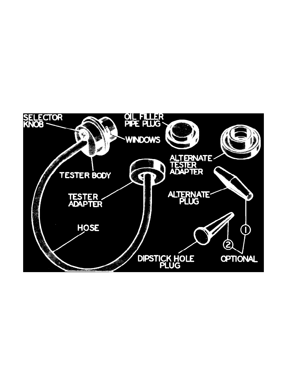
Fig. 35 AC positive crankcase ventilation system tester
SYSTEM TESTING WITH TESTER
This test uses the AC positive crankcase ventilation tester, Fig. 35, which is operated by the engine vacuum through the oil filler opening.
1.
With engine at normal operating temperature, remove oil filler cap and dipstick.
2.
Connect one end of the hose to the tester body and connect the other end of the hose to the tester adapter.
3.
Use the dipstick hole plug to plug the opening in the dipstick tube.
4.
Insert the tester adapter in the filler cap opening and turn the selector knob to No. 2, Fig. 35.
5.
If the vehicle has a system with the tube from the air cleaner going into the oil filler cap, disconnect the tube at the filler cap and plug the tube.
6.
Start engine and let it idle.
7.
With plugs secure and tube free of kinks, hold tester body upright and note color in the tester windows. Following lists the various colors and
probable cause or related condition of the system.
Green