
Skylark V6-173 2.8L VIN X 2-bbl (1984)
Axle Beam: Service and Repair
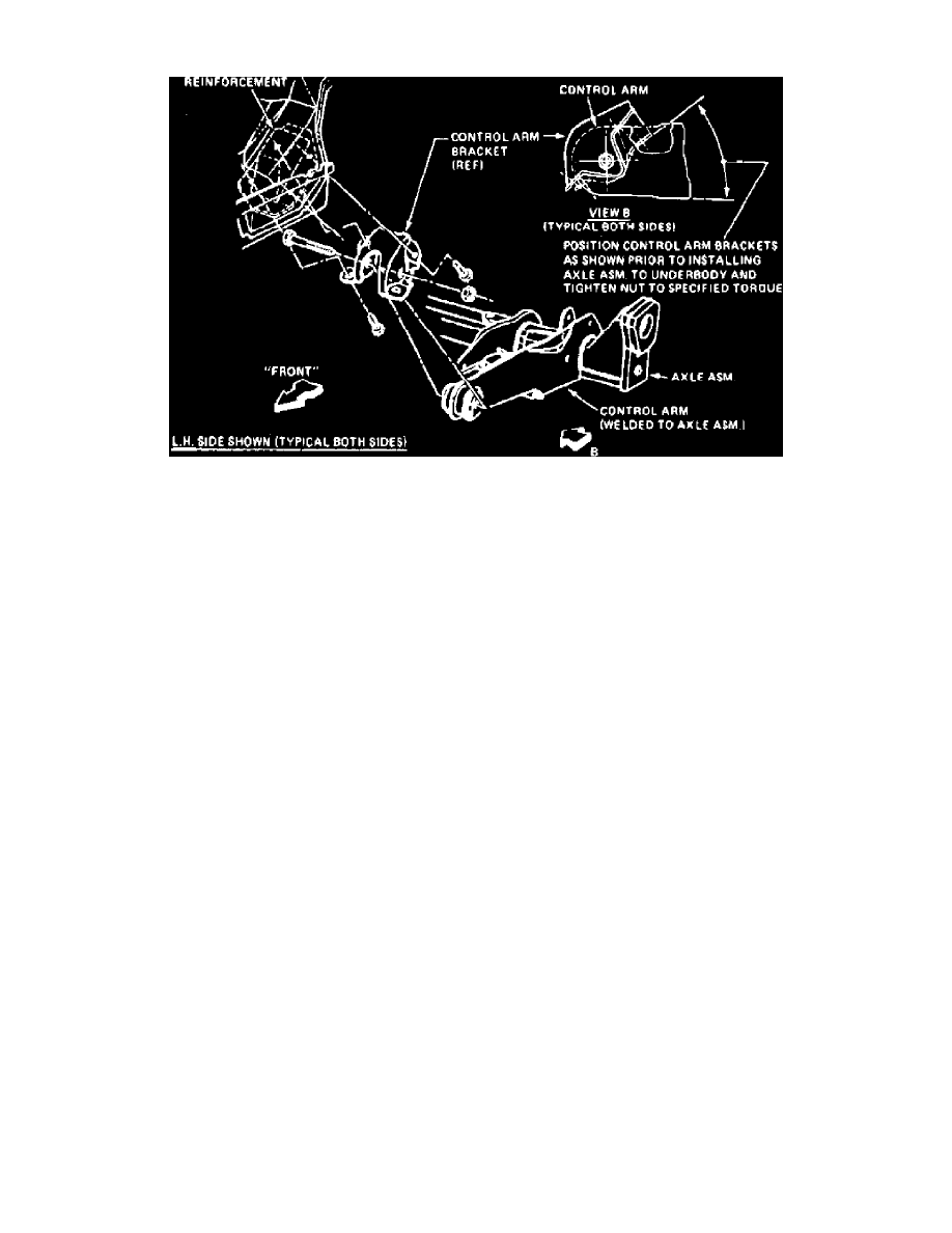
Fig. 2 Control arm bracket installation
When removing rear axle assembly, do not use twin-post type hoist. The swing arc tendency of this axle may cause it to slip from hoist. Perform axle
removal on floor if necessary.
1.
Raise rear of vehicle and support rear axle using a suitable jack.
2.
Remove rear wheel assembly and brake drum. Do not hammer on brake drum since damage to bearings may result.
3.
Disconnect parking brake cable at equalizer, then remove brake line brackets from frame.
4.
Disconnect shock absorber from lower mountings on axle housing.
5.
Remove track bar attaching nut and bolt and disconnect track bar. Do not suspend rear axle by brake hoses, otherwise damage to hoses may
result.
6.
Carefully lower rear axle assembly and remove coil spring and insulators.
7.
Disconnect brake lines from control arm attachments.
8.
Remove parking brake cable from rear axle attachments.
9.
Remove hub attaching bolts, then the hub and bearing assembly and position backing plate out of way.
10.
Remove control arm bracket to underbody attaching bolts, then lower axle assembly and remove from vehicle.
11.
Reverse procedure to install, noting the following:
a. If control arm brackets were removed from control arms, torque attaching nuts to 78 ft.lbs.
b. Install control arm bracket at a 40.5---44.5° angle as shown in Fig. 2.
c. Torque control arm-to-underbody attaching bolts to 28 ft.lbs.
d. Torque track bar attaching nut to 35 ft.lbs.