
Skylark V6-173 2.8L VIN Z 2-bbl HP (1982)
5.
Carefully assemble the clutch cover over the (3) gauges and onto the case, using (7) spacers placed evenly around the perimeter. Retain with
bolts provided. See Figure 7B-33A.
Draw the cover to the case by tightening alternately and gradually. Torque bolts to 10 ft.lbs. (12 N-m.). This will compress all three gauge
sleeves.
6.
Rotate each gauge to seat the bearing. Rotate the differential case through three revolutions in each direction.
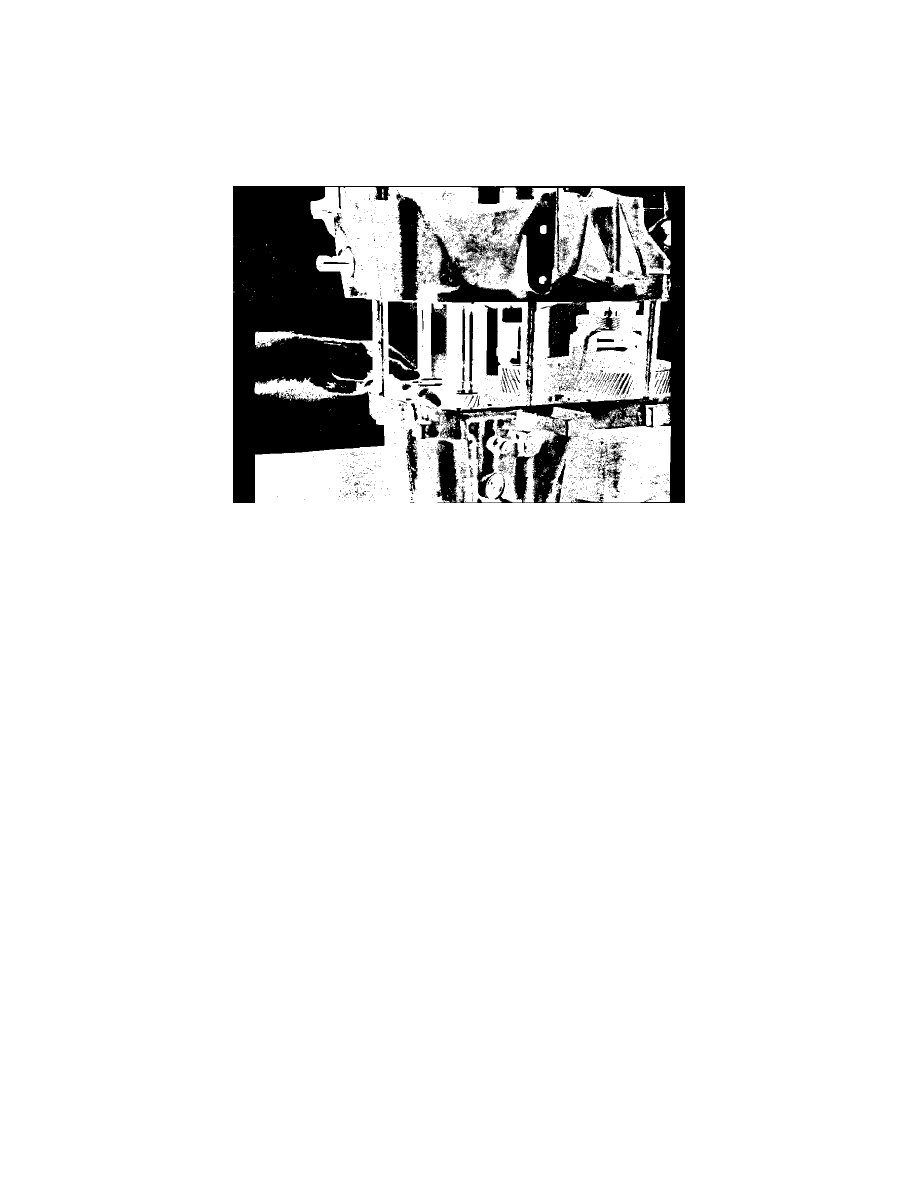
FIGURE 7B-34A
7.
With the three gauges compressed, the gap between the outer sleeve and the base pad is larger than the correct preload shim at each location.
Carefully compare the gap to the available shims. Determine the largest shim that can be placed into differential gap and drawn through
without binding. Use the next size smaller shim for this location. Repeat procedure to select output shaft shim. On the input shaft, repeat this
procedure and use a shim 2 sizes smaller than the largest shim that can be drawn through without binding. See Figure 7B-34A.
8.
When each of the three shims has been selected, remove the clutch cover, spacers (7) and gauges (3).
9.
Place the selected shims into their respective bores in the clutch cover, add the metal shield and then install the bearing cups using special
tool J-26936 on input shaft and J-23423-A on output shaft cup and J-26938 on the differential side bearing cup.
10.
After assembly, check end play of input shaft. If any end play is present, replace shim with next size larger at this location.
11.
Reinstall transaxle in car and perform shift cable adjustment as outlined previously.