
Skylark V6-204 3.3L VIN N FI (1989)
Crankshaft Position Sensor: Description and Operation
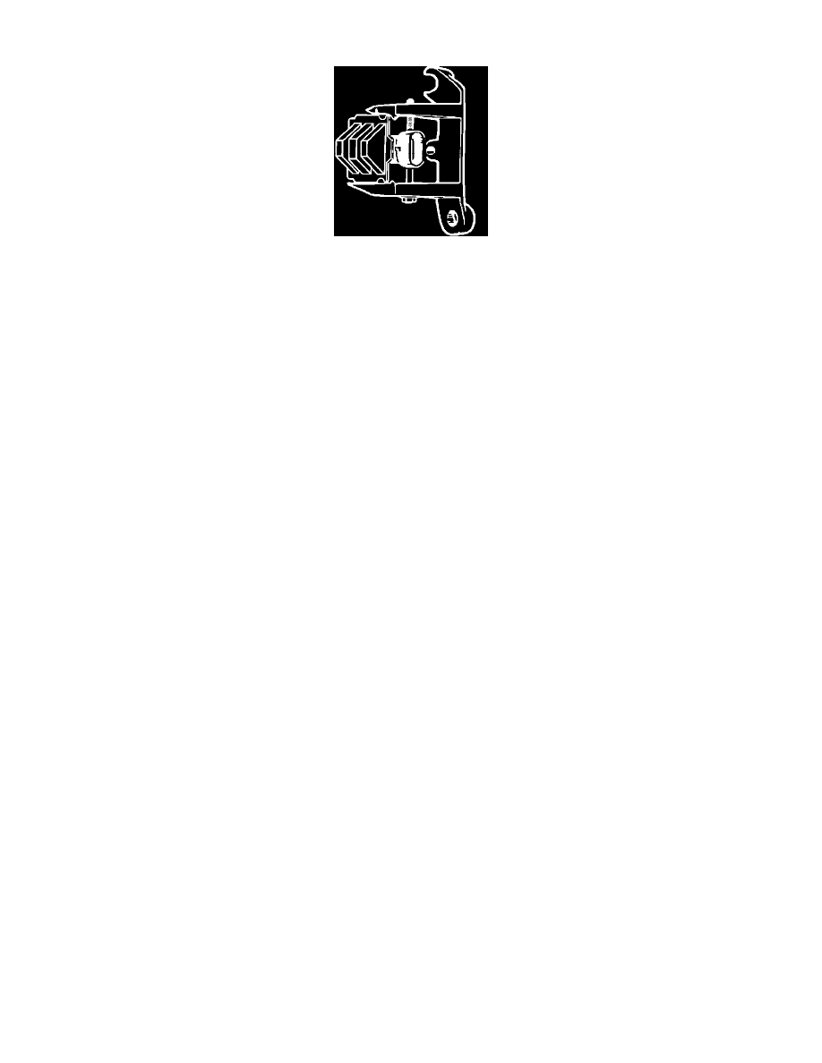
Dual Crankshaft Sensor
The C3I dual crank sensor is mounted in a pedestal near the harmonic balancer. The sensor consist of two Hall-Effect switches, which depend on two
metal interrupter rings mounted on the harmonic balancer to activate them. Windows in the interrupter rings activate the Hall-Effect switches as they
provide a path for the magnetic field between the switches, transducers and magnets. When one of the Hall-Effect switches is activated, it grounds the
signal line to the C3I module, pulling that signals line (sync pulse or crank pulse ) applied voltage low, which is interpreted as a signal. Because of the
way the signal is created by the dual crank sensor, the signal voltage is either at a high or low voltage which creates a square wave.
Three crank signal pulses and one sync pulse are created during each crankshaft revolution. The crank signal is used by the C3I module to create a
square wave reference signal to send to the ECM. The ECM can then calculate RPM and crankshaft position based on this signal from the C3I module.
The sync pulse is used by the C3I module to begin the ignition coil firing sequence starting with the #3/6 coil. The firing starts at this coil combination
because either piston #3 or #6 is on the compression stroke. Both the crank and sync pulse signals must be received by the ignition module in order for
the engine to start. A bent interrupter ring or a mis-adjusted dual crank sensor could cause a no start condition, rough idle or poor performance problem.