
Somerset V6-181 3.0L (1986)
Blower Motor: Symptom Related Diagnostic Procedures
System Diagnosis
NOTE: Perform the Blower Motor Test with the Ignition Switch in RUN, the Mode Selector in VENT, and the Blower Switch in HI.
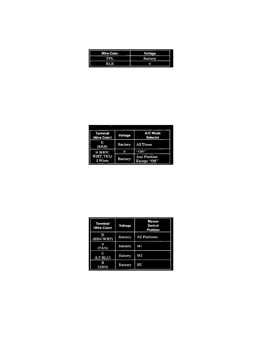
1. BLOWER MOTOR TEST: Check the HTR A/C FUSE. Measure the voltages to ground at the BLOWER MOTOR with the connector in place.
Blower Motor Test.
^
If the voltages at the motor are correct, connector pins are not loose, and the motor does not run, install a new BLOWER MOTOR.
^
If Battery voltage is present at the PPL wire, check the wire for opens, then test the Function Selector and the BLOWER RELAY.
^
If Battery voltage is at the BLK wire, check for an open ground.
NOTE: The A/C Mode Selector Test is to be performed with the Ignition Switch in RUN.
2. A/C MODE SELECTOR TEST: Backprobe the connector to the A/C CONNECTOR HEAD and measure the voltage to ground, with the
connector still on the head.
A/C Control Head Test.
^
If Battery voltage is not present at E, check the BRN wire circuit back to the fuse.
^
If Battery voltage is at E, but not at B, install a new A/C CONTROL HEAD.
NOTE: The Blower Switch Test is to be performed with the A/C Mode Selector in VENT, and the Ignition Switch in RUN.
3. BLOWER SWITCH TEST: Remove the connector from the BLOWER RESISTORS. Measure the voltage to ground on the connector to the A/C
CONTROL HEAD, with the connector still on the head.
A/C Control Head Test.
^
If any of the voltages above are not correct, install a new A/C CONTROL HEAD.
NOTE: The Blower Resistors Test is to be performed with the Ignition Switch in RUN, and the Blower Switch in LO.
4. BLOWER RESISTORS TEST: Backprobe the connector to the BLOWER RESISTORS with the connector still on the resistors, and measure the
resistance between the wires listed below. The resistance values are approximate.