
Somerset V6-181 3.0L (1986)
Fuel System Diagnosis
CHART A-7 - FUEL SYSTEM DIAGNOSIS (PART 1 OF 2)
Circuit Description:
When the ignition switch is turned "ON", the Electronic Control Module (ECM) will turn "ON" the in-tank fuel pump. It will remain "ON" as long as the
engine is cranking or running, and the ECM is receiving HEI distributor reference pulses.
If there are no reference pulses, the ECM will shut "OFF" the fuel pump within 2 seconds after key "ON" or engine stopped.
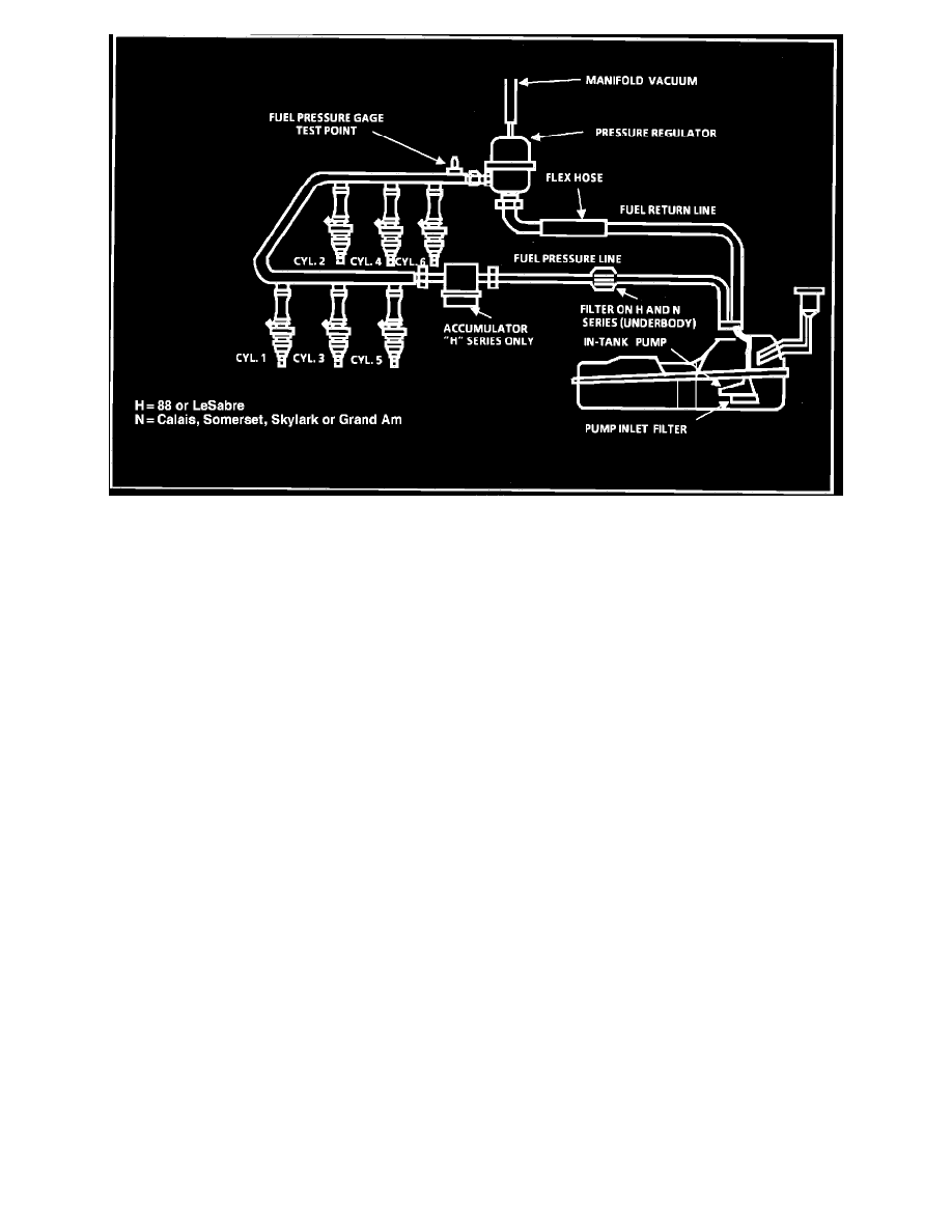
The pump will deliver fuel to the fuel rail and injectors, then to the pressure regulator, where the system pressure is controlled to 179 to 317 kPa (26 to
46 psi). Excess fuel is then returned to the fuel tank.
Test Description:
Numbers below refer to circled numbers on the diagnostic chart.
1.
Use pressure gage J-34730-1. Wrap a shop towel around the fuel pressure tap to absorb any small amount of fuel leakage that may occur when
installing the gage. Ignition "ON" pump pressure should be 255-298 kPa (37-43 psi). This pressure is controlled by spring pressure within the
regulator assembly.
2.
When the engine is idling, the manifold pressure is low (high vacuum) and is applied to the fuel regulator diaphragm.
This will offset the spring and result in a lower fuel pressure, 228-278 kPa (33-40 psi). This idle pressure will vary somewhat, depending on
barometric pressure, however, the pressure idling was less, indicating pressure regulator control. If fuel is observed in vacuum hose to pressure
regulator, the regulator is faulty and must be replaced.
3.
Pressure that continues to fall is caused by one of the following:
^
In-tank fuel pump check valve not holding.
^
Pump coupling hose leaking.
^
Fuel pressure regulator valve leaking.
^
Injector sticking open.