
Terraza FWD V6-3.5L VIN 8 (2005)
14. Remove the CPA (3) from the LF/driver side impact module yellow connector (3) which is located under the driver seat.
15. Disconnect the vehicle harness connector (4) from the LF side impact module connector (1).
16. Remove the passenger/right I/P insulator panel.
17. Remove the CPA (2) from the I/P module yellow connector (1).
18. Disconnect the I/P module connector (1).
19. Remove the passenger/right lower center pillar trim cover.
20. Remove the CPA from the right seat belt retractor pretensioner connector.
21. Remove the vehicle wiring harness connector from the right seat belt retractor pretensioner.
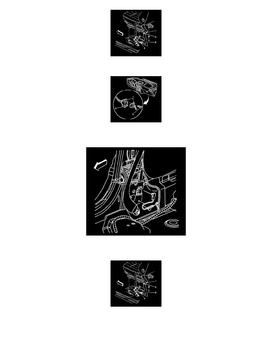
22. Remove the CPA (3) from the RF/passenger side impact module yellow connector (3) which is located under the passenger seat.
23. Disconnect the vehicle harness connector (4) from the RF side impact module connector (1).
ENABLING PROCEDURE
1. Remove the key from the ignition.