
Terraza FWD V6-3.5L VIN L (2006)
2. Disconnect the connector from the component.
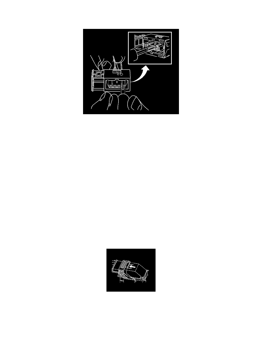
3. Remove the wire dress cover, if necessary.
4. Push the wire side of the terminal that is being removed toward the connector and hold it in position.
5. Insert the J 38125-557 (GM P/N 12122378) into the 2 cavities on each side of the terminal at the front of the connector and push until you feel the
tool disengage the terminal retainers. See the release tool cross reference in the Reference Guide of the J-38125 to ensure that the correct release
tool is used.
6. Carefully pull the terminal out of the connector. Always remember never use force when pulling a terminal out of a connector. If the terminal is
difficult to remove, repeat the entire procedure.
TERMINAL REPAIR PROCEDURE
Use the appropriate terminal and follow the instructions in the J-38125 .
Connector Position Assurance Locks
CONNECTOR POSITION ASSURANCE LOCKS
The connector position assurance (CPA) is a small plastic insert that fits through the locking tabs of the connector. CPAs are used in various connectors
throughout the vehicle. CPAs are also used in all SIR system electrical connectors. The CPA ensures that the connector halves cannot vibrate apart. You
must have the CPA in place in order to ensure good contact between the mating terminals, of the connector.
Delphi Connectors (Micro .64)
DELPHI CONNECTORS (MICRO .64)
TOOLS REQUIRED
J-38125 Terminal Repair Kit
REMOVAL PROCEDURE
Follow the steps below in order to remove terminals from Micro 64 connectors.
1. Locate the lever lock on the wire dress cover. While depressing the lock, pull the lever over and past the lock.
2. Disconnect the connector from the component.