
Allante V8-273 4.5L (1991)
Control Valve Assembly
REMOVE OR DISCONNECT
1. Negative battery cable.
2. Transaxle case side cover.
3. Wring harness as needed.
4. Oil pump.
5. Bolts (132, fig. 5) and servo pipe retainer (133) from valve body.
NOTE: After the bolt and retainer are removed, secure the servo pipes (135 & 136) as shown in figure 5. Place a rubber band over the holding
fixture and stretch over pipes. This will allow for easy disassembly.
6. Attaching bolts (40, 41, 43 & 55, fig. 6).
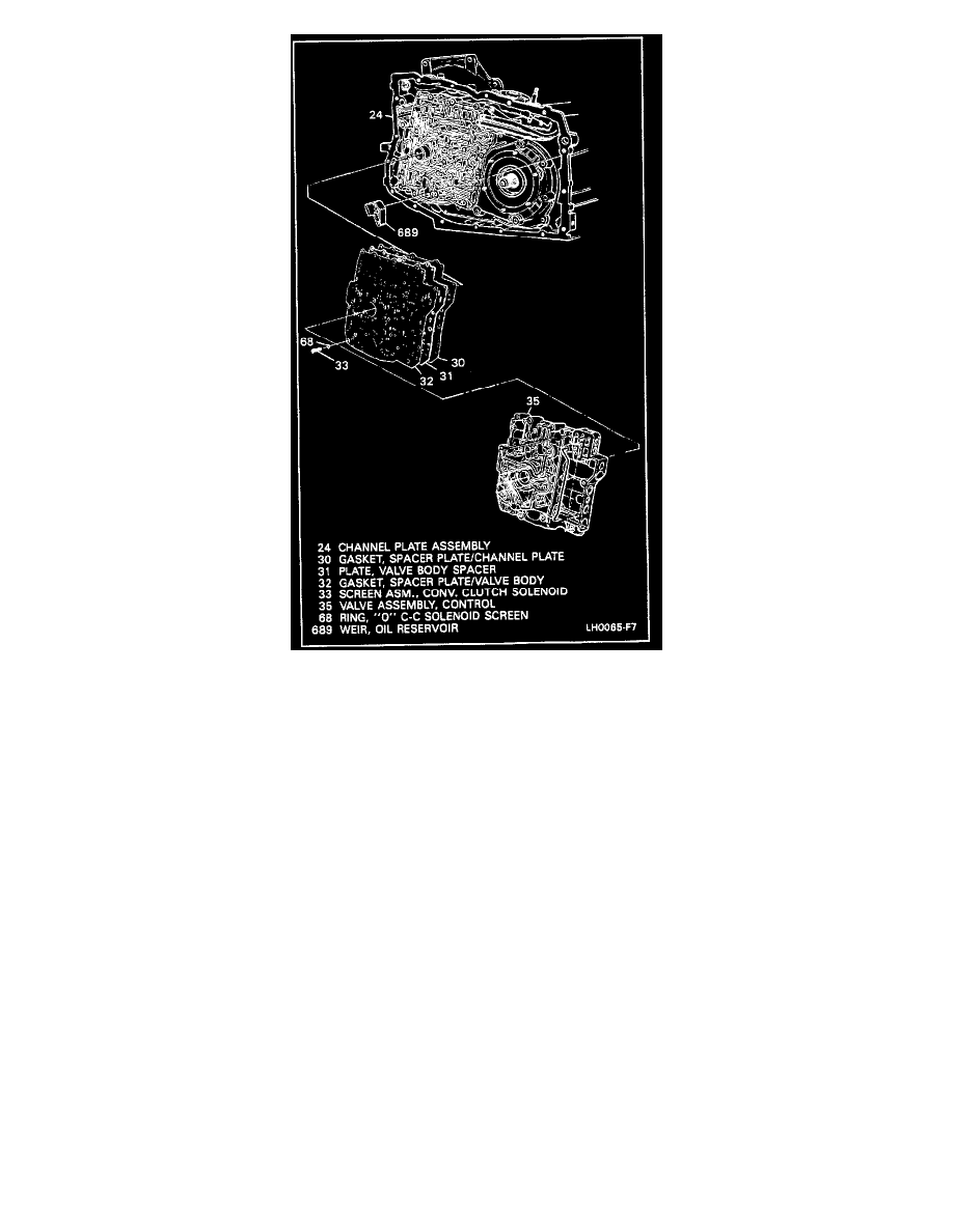
7. Control valve assembly (35, fig. 7) from channel plate (24).
8. Oil weir (689, fig. 7).
9. Four check balls from spacer plate, put back in control valve assembly.
10. Spacer plate and gaskets (30, 31 & 32, fig. 3 & 7).
11. Eight check balls (fig. 1) from channel plate.