
Allante V8-273 4.5L (1991)
Control Valve Assembly
REMOVE
1. Case side cover.
2. Wiring harness.
3. Bolts (327, fig. 1 & 2) retaining solenoid.
4. Solenoid (328, fig. 2) and O-ring (329, fig. 2).
CLEAN AND INSPECT:
-
O-ring.
-
Solenoid.
-
Valve body passage.
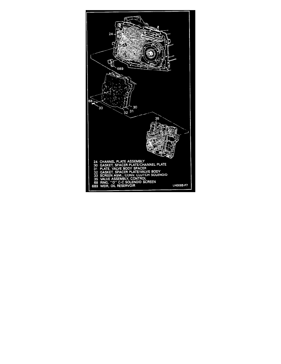
NOTE: There is a screen inside the valve body. Refer to 33, figure 3. This screen does not normally need to be replaced.
INSTALL OR CONNECT
1. Solenoid (328, fig. 2) and O-ring (329, fig. 2).
2. Bolts (327, fig. 1 & 2) retaining solenoid. Torque to 8.0 - 14 Nm (6 - 10 ft lbs).
3. Wiring harness.
4. Case side cover.
ADJUST