
Catera V6-3.0L VIN R (1997)
Transmission Temperature Sensor/Switch: Diagram Information and Instructions
Electrical Schematics
The wiring schematic is the cornerstone of electrical diagnosis. Schematics break the entire electrical system down into individual circuits, showing the
electrical current paths when a circuit is operating properly. Wiring which is not part of the circuit of interest is referenced to another diagram, where the
circuit is shown complete. Schematics use a top (power) to bottom (ground) sequence to present electrical information.
IMPORTANT: It is important to realize that no attempt is made on the schematic to represent components and wiring as they physically appear on the
vehicle. For example, a 4-foot length of wire is treated no differently in a schematic from one which is only a few inches long.
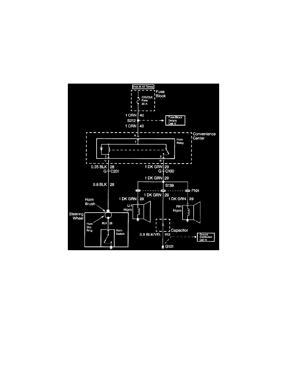
When diagnosing a horn problem, the technician would refer to Horn. This schematic is a typical example of what would be found at Horn, along with
the included text.
Wiring Systems
Voltage is applied to the Horn Relay at all times. When the relay coil is grounded by closing the Horn Switch, the relay contacts close. When the relay
contacts are closed, both the LH and RH Horns are energized.