
Cimarron V6-173 2.8L (1986)
Fuel System Diagnosis
CHART A-7 - FUEL SYSTEM DIAGNOSIS (PART 1 OF 2)
(CONTINUED FROM A-3)
Circuit Description:
When the ignition switch is turned "ON", the Electronic Control Module (ECM) will turn "ON" the in-tank fuel pump. It will remain "ON" as long as the
engine is cranking or running, and the ECM is receiving HEI distributor reference pulses.
If there are no reference pulses, the ECM will shut "OFF" the fuel pump within 2 seconds after ignition "ON" or engine stops.
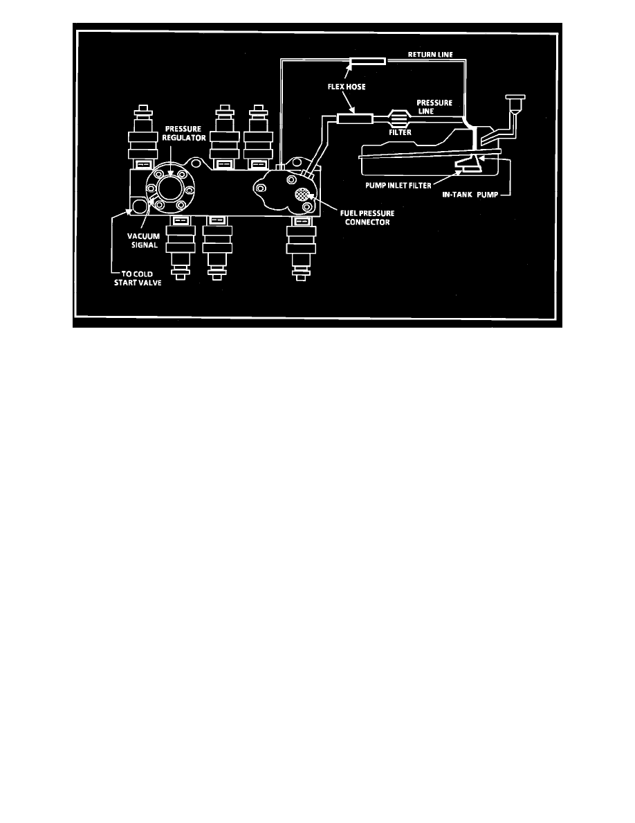
The pump will deliver fuel to the fuel rail and injectors, then to the pressure regulator, where the system pressure is controlled to about 234 to 317 kPa
(34 to 46 psi). Excess fuel is then returned to the fuel tank.
Test Description:
Numbers below refer to circled numbers on the diagnostic chart.
1.
Use pressure gage J-34730-1. Wrap a shop towel around the fuel pressure connector to absorb any small amount of fuel leakage that may occur
when installing the gage. Ignition "ON" pump pressure should be 280-325 kPa (40.5-47 psi). This pressure is controlled by spring pressure within
the regulator assembly.
2.
When the engine is idling, the manifold pressure is low (high vacuum) and is applied to the fuel regulator diaphragm. This will offset the spring and
result in a lower fuel pressure. This idle pressure will vary somewhat depending on barometric pressure, however, the pressure idling should be less
indicating pressure regulator control.
3.
Pressure that continues to fall is caused by one of the following:
^
In-tank fuel pump check valve not holding
^
Pump coupling hose or pulsator leaking
^
Fuel pressure regulator valve leaking
^
Injector or cold start valve sticking open
4.
An injector sticking open can best be determined by checking for a fouled or saturated spark plugs) If a leaking injector can not be determined by a
fouled or saturated spark plug the following procedure should be used.
^
Remove Plenum, cold start valve and remove fuel rail bolts. Follow the procedures in the fuel control section of this manual, but leave fuel