
CTS-V V8-6.0L VIN U (2006)
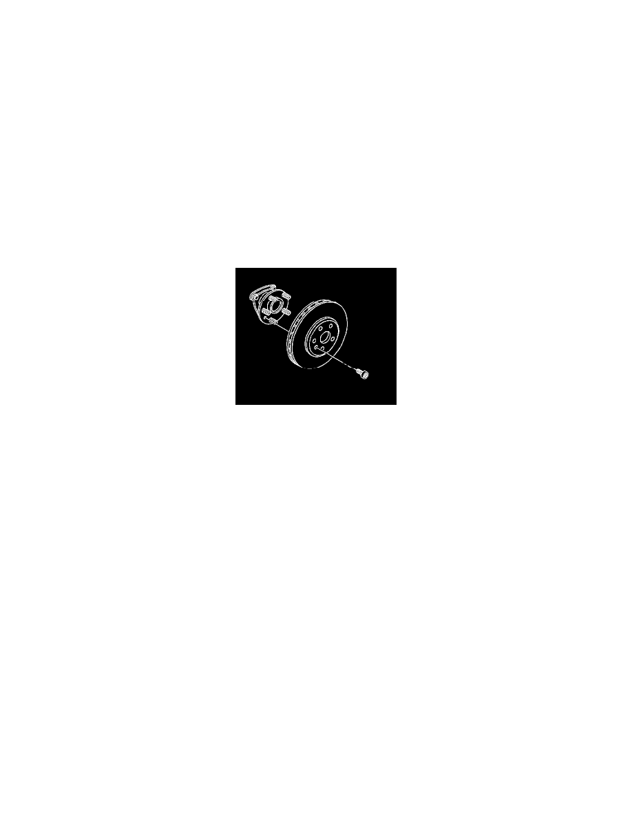
3. Using J-46277 and J 2619-01 remove the rotor from the hub assembly.
4. Inspect the park brake components for the following conditions:
^
Bent or broken hold down spring
^
Broken, cracked or worn brake shoe lining
^
Bent or damaged brake shoe
^
Worn, bent or damaged backing plate
5. If any of these conditions are found replace the affected parts.
Installation Procedure
1. Important: Whenever the brake rotor has been separated from the hub/axle flange, any rust or contaminants should be cleaned from the hub/axle
flange and the brake rotor mating surfaces. Failure to do this may result in excessive assembled lateral runout (LRO) of the brake rotor, which
could lead to brake pulsation.
Using the J 42450-A, thoroughly clean any rust or corrosion from the mating surface of the hub/axle flange.
2. Using the J 41013, thoroughly clean any rust or corrosion from the mating surface and mounting surface of the brake rotor.
3. Inspect the mating surfaces of the hub/axle flange and the rotor to ensure that there are no foreign particles or debris remaining.
4. If installing a new brake rotor, adjust the clearance of the parking brake shoe to the drum-in-hat portion of the brake rotor. Refer to Park Brake
Adjustment in Park Brake.
5. Install the brake rotor to the hub/axle flange. Use the matchmark made prior to removal for proper orientation to the flange.
6. Notice: Refer to Fastener Notice in Service Precautions.
Install the brake rotor mounting screw.
^
Tighten the brake rotor mounting screw to 14 Nm (124 inch lbs.).
7. If the brake rotor was removed and installed as part of a brake system repair, measure the assembled lateral runout (LRO) of the brake rotor to
ensure optimum performance of the disc brakes. Refer to Brake Rotor Assembled Lateral Runout (LRO) Measurement. See: Testing and
Inspection/Brake Rotor Assembled Lateral Runout Measurement
8. If the brake rotor assembled LRO measurement exceeds the specification, bring the LRO to within specifications. Refer to Brake Rotor Assembled
Lateral Runout (LRO) Correction. See: Testing and Inspection/Brake Rotor Assembled Lateral Runout Correction
9. Install the brake caliper and the brake caliper bracket as an assembly to the suspension knuckle.
10. Install the tire and wheel assembly.
11. Lower the vehicle.
12. If the brake rotor was refinished or replaced, or if new brake pads were installed, burnish the pads and rotors. Refer to Burnishing Pads and
Rotors.