
CTS V6-3.2L VIN N (2003)
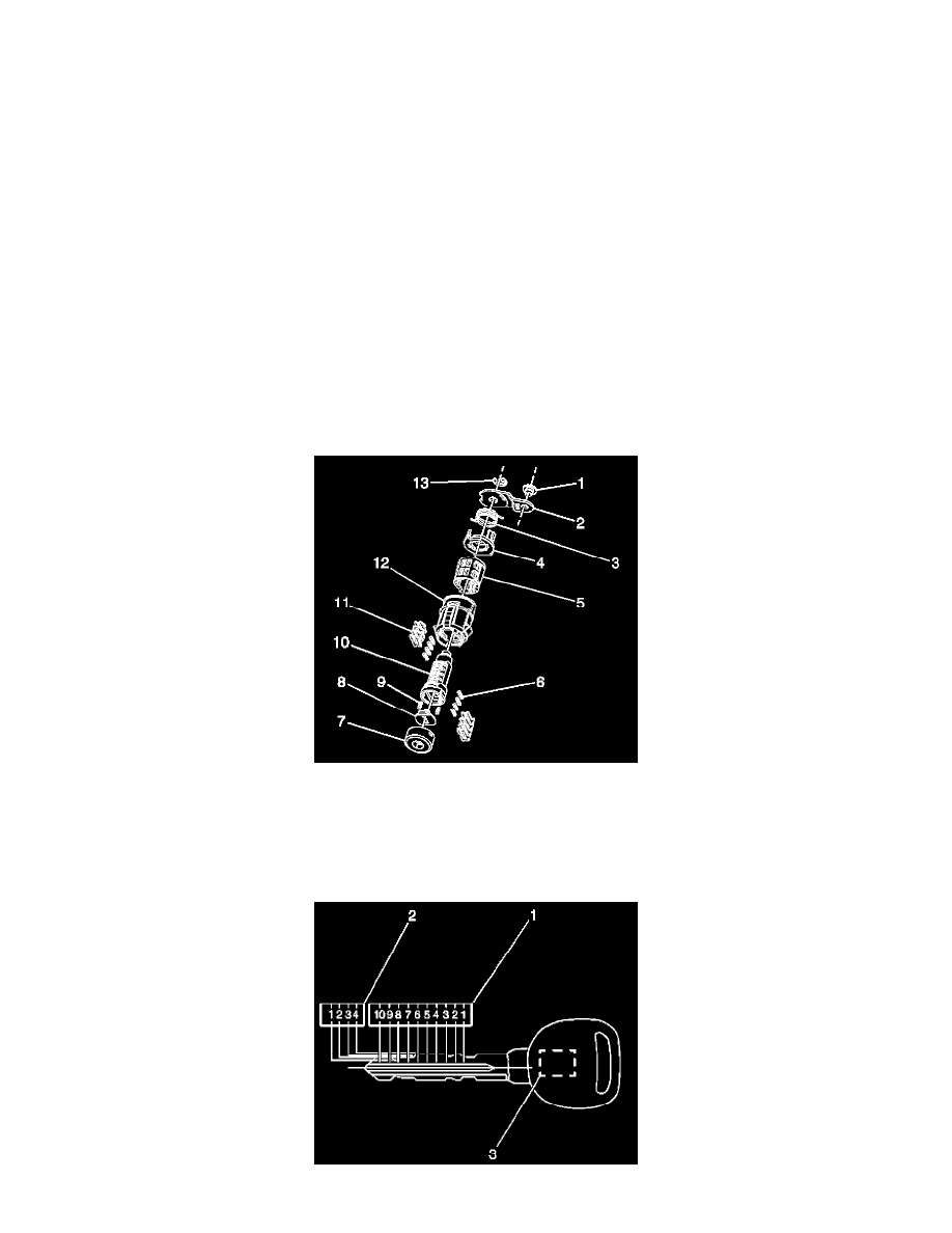
12. Hold the case assembly (11) with the pre-staked detent spring retainer facing downward.
13. First insert one detent spring (3) then one detent ball (4) into the detent spring hole located to the rear and inside of the cylinder case assembly
(11). The detent spring (3) and the detent ball (4) are not self-retaining and must be held in place until the coded cylinder is installed into the case
assembly.
14. With the matching key fully inserted into the coded cylinder install the coded cylinder into the case assembly (11). Insure the detent spring (3) and
detent ball (4) are held in place until the coded cylinder is fully installed. The detent (4) should line with the v-shaped groove on the rear of the
cylinder which will prevent the detent spring and detent fall from falling out of the case assembly.
15. Remove the matching key being careful to keep the coded cylinder (9) fully inserted into the case assembly (11).
16. Insert one shutter spring (8) each into the two shutter spring holes located on the front face of the cylinder (9).
17. Install the shutter assembly (7) into the recessed area in the front face of the cylinder (9). Ensure that the ends of the pin on the shutter assembly
(7) are positioned in the pin cavities located on the front face of the cylinder (9).
18. Install the lock cylinder cap (6) by aligning the two notches in the cap with the drain hole located on the bottom of the case assembly (11) and the
corresponding feature located on the top of the case assembly. Snap the cap (6) into place with light hand pressure. Insure the cap is securely
retained on the case assembly and that the shutter springs (8) push the shutter assembly (7) up against the inside surface of the cap.
19. Install the appropriate lever (12) in the groove at the end of the cylinder (9) to secure the lever (2) to the cylinder.
20. Install the retaining ring (12) in the groove at the end of the cylinder (9) to secure the lever (2) to the cylinder.
21. Snap the appropriate rod retainer (1) right or left into the hole in the lever (2).
ASSEMBLING AND CODING THE FREE-WHEELING FRONT SIDE DOOR LOCK CYLINDER
The free-wheeling front side door lock cylinder uses eight of the ten key cut positions, 3-10. The tumbler positions are staggered from side to side with
four on one side. The right and left side door lock are identical except for the lever (3) and rod retainer (13). The right lever is color-coded, yellow and
stamped with the letter R001 and the left lever is color-coded olive drab and stamped with the letter L001. The right rod retainer is color coded yellow
and the left rod retainer is color coded green. This determine on which side of the vehicle the lock cylinder will be installed.
1. Hold the uncoded cylinder (10) positioned so the sidebar is facing to the left and the four spring wells is facing upward.
IMPORTANT: The free-wheeling front side door lock cylinder tumblers (11) are not self retaining and must be held in place if the key is not fully
inserted into the lock cylinder or until the cylinder (10) is assembled into the case (12).
2. Insert one tumbler spring (6) into the four tumbler spring wells.