
CTS V6-3.2L VIN N (2003)
Manifold Absolute Pressure (MAP) Sensor: Testing and Inspection
INTAKE MANIFOLD RUNNER CONTROL SYSTEM DIAGNOSIS
CIRCUIT DESCRIPTION
The multi-ram system uses variable air induction tuning in order to achieve maximum performance and efficiency over the entire operating range of
the engine. The system consists of two main parts: the intake manifold runner control valve and the intake manifold tuning valve. The engine control
module (ECM) controls two solenoids that apply vacuum to each of the valve actuators. When the ECM commands the solenoid ON, vacuum is
supplied to that actuator, causing the valve to open or close. Vacuum is supplied to each of the solenoids from a vacuum reservoir located near the
intake air duct. The reservoir is required to maintain the vacuum supply during extended acceleration conditions. The intake manifold contains the
intake manifold runner control valve. This vacuum operated valve is a moveable divider that changes the airflow characteristics of the intake manifold.
The second part of the multi-ram system is the intake manifold tuning valve. This vacuum operated valve is located in the air intake duct assembly.
This is a moveable divider that changes the tuning of the air intake system. By opening and closing these valves independently, in different
combinations, four different air flow configurations can be created, each optimizing a set of engine operating conditions.
Both solenoid valves are supplied switched battery power from the engine controls power relay. Both solenoid valves have a control circuit to the
ECM. The ECM controls a valve by grounding the control circuit. If a fault is detected with either of the solenoid valve control circuits, a diagnostic
trouble code (DTC) will set.
TEST DESCRIPTION
The number below refer to the step number on the diagnostic table.
5. This step is to confirm that the valve inside the housing is moving correctly and is not loose or damaged in any way.
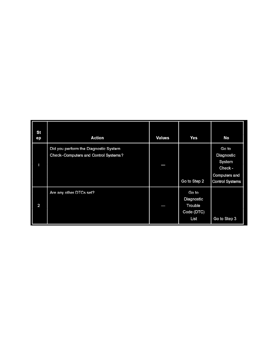
Steps 1-2