
CTS RWD V6-3.6L (2008)
*
The electrical harness
*
The steering knuckle assembly
*
The brake pipes
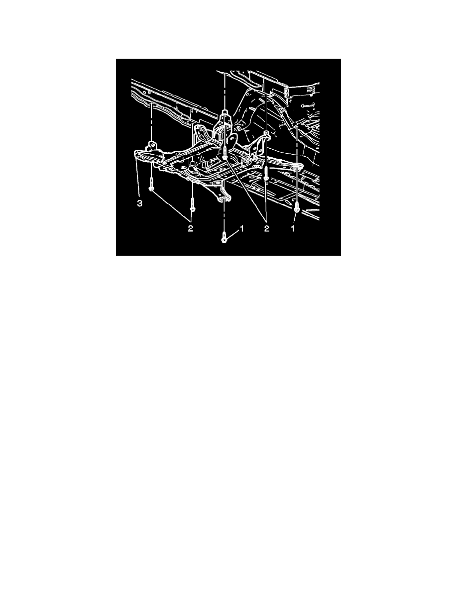
Notice: Refer to Fastener Notice (See: Service Precautions/Vehicle Damage Warnings/Fastener Notice) .
6. Install the frame mountings bolts (2).
Tighten the bolts to 191 N.m (141 lb ft).
7. Raise the vehicle.
8. Install the engine mount lower retaining nuts (2).
Tighten the nuts to 50 N.m (37 lb ft).
9. Remove the J 39580 from under the vehicle.
10. Remove the mechanics wire supporting the power steering gear.
11. Install the shock module yokes to the lower control arms. Refer to Front Shock Absorber Yoke Replacement (See: Steering and
Suspension/Suspension/Suspension Strut / Shock Absorber/Service and Repair/Front Suspension Shock Absorber/Front Shock Absorber Yoke
Replacement) .
12. Install the power steering gear mounting bolts. Refer to Steering Gear Replacement (with All Wheel Drive) (See: Steering and
Suspension/Steering/Steering Gear/Service and Repair)Steering Gear Replacement (with Rear Wheel Drive) (See: Steering and
Suspension/Steering/Steering Gear/Service and Repair) .
13. Install the ball joint to the steering knuckle. Refer to Lower Control Arm Replacement (AWD) (See: Steering and Suspension/Suspension/Control
Arm/Service and Repair/Front Suspension)Lower Control Arm Replacement (RWD) (See: Steering and Suspension/Suspension/Control
Arm/Service and Repair/Front Suspension) .
14. Install the outer tie rod to the steering knuckle. Refer to Steering Linkage Outer Tie Rod Replacement (with Rear Wheel Drive) (See: Steering and
Suspension/Steering/Tie Rod/Service and Repair/Steering Linkage Outer Tie Rod Replacement (with Rear Wheel Drive))Steering Linkage Outer
Tie Rod Replacement (with All Wheel Drive) (See: Steering and Suspension/Steering/Tie Rod/Service and Repair/Steering Linkage Outer Tie
Rod Replacement (with All Wheel Drive)) .
Important: Ensure correct position from the previously marked spots.
15. Tighten the stabilizer shaft bolts.
Tighten the bolts to 60 N.m (44 lb ft).
16. Install the stabilizer shaft link to the lower control arms. Refer to Stabilizer Shaft Link Replacement (AWD) (See: Steering and
Suspension/Suspension/Stabilizer Bar/Stabilizer Link/Service and Repair/Front Suspension)Stabilizer Shaft Link Replacement (RWD) (See:
Steering and Suspension/Suspension/Stabilizer Bar/Stabilizer Link/Service and Repair/Front Suspension) .