
CTS RWD V6-3.6L (2008)
Electronic Brake Control Module: Service and Repair
Electronic Brake Control Module Replacement
Removal Procedure
Notice: To prevent equipment damage, never connect or disconnect the wiring harness connection from the EBCM with the ignition switch in the ON
position.
Important:
*
The ignition switch must be placed in the OFF mode ONLY, before disconnecting the negative battery cable during this procedure. If the
ignition switch is accidentally placed into ignition ON engine OFF mode, the control modules will be activated and disconnecting the
negative cable will cause various DTCs to be set. Refer to Keyless Entry System Description and Operation (without RPO Y41) (See:
Accessories and Optional Equipment/Antitheft and Alarm Systems/Keyless Entry/Description and Operation/Keyless Entry System Description
and Operation (without RPO Y41))Keyless Entry System Description and Operation (with RPO Y41) (See: Accessories and Optional
Equipment/Antitheft and Alarm Systems/Keyless Entry/Description and Operation/Keyless Entry System Description and Operation (with RPO
Y41)) .
*
After the ignition switch is placed into OFF mode, a waiting period of 2 minutes must be observed to allow the high-speed LAN control
modules to deactivate before disconnecting or connecting the negative battery cable during this procedure. If the waiting period is not
observed, one or more of these control modules may still be activated, causing various DTCs to be set.
1. Place the ignition switch into OFF mode. DO NOT place the ignition switch into ignition ON engine OFF mode.
2. Wait a minimum of 2 minutes to allow the high-speed LAN control modules to deactivate.
3. Disconnect the negative battery cable. Refer to Battery Negative Cable Disconnection and Connection (Side Post) (See: Starting and
Charging/Battery/Battery Cable/Service and Repair) .
4. Raise and support the vehicle. Refer to Lifting and Jacking the Vehicle (See: Maintenance/Vehicle Lifting/Service and Repair) .
5. Remove the front air deflector shield. Refer to Front Air Deflector Replacement (See: Body and Frame/Spoilers, Flaps, and Air Dams/Air
Dam/Service and Repair/Front Air Deflector Replacement) .
6. Remove the washer solvent container fasteners and position the washer solvent container aside to access the electronic brake control module
(EBCM). Refer to Windshield Washer Solvent Container Replacement (Minus CE4) (See: Wiper and Washer Systems/Windshield Washer
Reservoir/Service and Repair/Windshield Washer Solvent Container Replacement (Minus CE4))Windshield Washer Solvent Container
Replacement (With CE4) (See: Wiper and Washer Systems/Windshield Washer Reservoir/Service and Repair/Windshield Washer Solvent
Container Replacement (With CE4)) .
7. Thoroughly clean the area around the EBCM of all dirt and debris.
8. Release the EBCM electrical connector by pressing the retaining tab and rotating the locking lever forward.
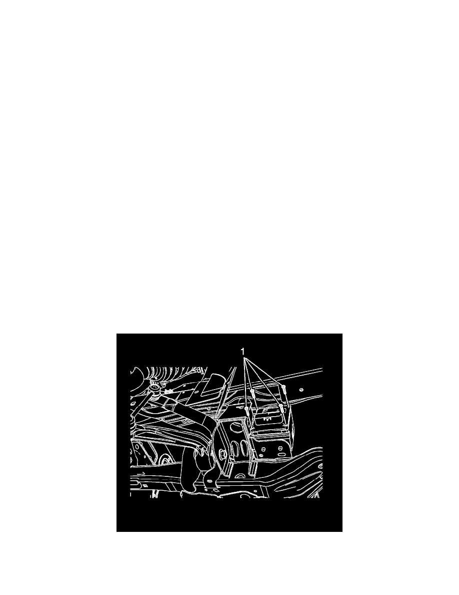
9. Remove the EBCM screws (1).