
CTS RWD V6-3.6L (2008)
Hydraulic Control Assembly - Antilock Brakes: Service and Repair
Brake Pressure Modulator Valve Replacement
Removal Procedure
Caution: Refer to Brake Fluid Irritant Caution (See: Service Precautions/Technician Safety Information/Brake Fluid Irritant Caution) .
Notice: Refer to Brake Fluid Effects on Paint and Electrical Components Notice (See: Service Precautions/Vehicle Damage Warnings) .
Notice: To prevent equipment damage, never connect or disconnect the wiring harness connection from the EBCM with the ignition switch in the ON
position.
Important:
*
The ignition switch must be placed in the OFF mode ONLY, before disconnecting the negative battery cable during this procedure. If the
ignition switch is accidentally placed into ignition ON engine OFF mode, the control modules will be activated and disconnecting the
negative cable will cause various DTCs to be set. Refer to Keyless Entry System Description and Operation (without RPO Y41) (See:
Accessories and Optional Equipment/Antitheft and Alarm Systems/Keyless Entry/Description and Operation/Keyless Entry System Description
and Operation (without RPO Y41))Keyless Entry System Description and Operation (with RPO Y41) (See: Accessories and Optional
Equipment/Antitheft and Alarm Systems/Keyless Entry/Description and Operation/Keyless Entry System Description and Operation (with RPO
Y41)) .
*
After the ignition switch is placed into OFF mode, a waiting period of 2 minutes must be observed to allow the high-speed LAN control
modules to deactivate before disconnecting or connecting the negative battery cable during this procedure. If the waiting period is not
observed, one or more of these control modules may still be activated, causing various DTCs to be set.
1. Place the ignition switch into OFF mode. DO NOT place the ignition switch into ignition ON engine OFF mode.
2. Wait a minimum of 2 minutes to allow the high-speed LAN control modules to deactivate.
3. Disconnect the negative battery cable. Refer to Battery Negative Cable Disconnection and Connection (Side Post) (See: Starting and
Charging/Battery/Battery Cable/Service and Repair) .
4. Remove the RH front compartment sight shield. Refer to Front Compartment Sight Shields Replacement (See: Body and Frame/Spoilers, Flaps,
and Air Dams/Air Dam/Service and Repair/Front Compartment Sight Shields Replacement) .
5. Thoroughly clean the area around the EBCM of all dirt and debris.
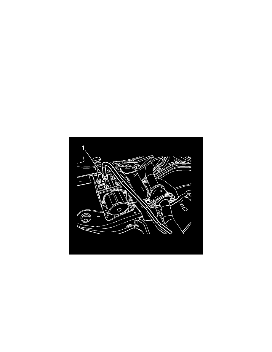
6. Disconnect the secondary brake pressure modulator valve (BPMV) inlet brake pipe fitting (1).
Cap the brake pipe fitting and plug the BPMV inlet port to prevent brake fluid loss and contamination.