
CTS RWD V6-3.6L (2008)
of the cylinder, which will prevent the detent spring and detent ball from falling out of the case assembly.
15. Remove the matching key being careful to keep the coded cylinder (1) fully inserted into the case assembly (4).
16. Insert one shutter spring (7) each into the 2 shutter spring holes located on the front face of the cylinder (1).
17. Install the shutter assembly (8) into the recessed area on the front face of the cylinder (1). Be sure that the ends of the pin on the shutter assembly
are positioned in the pin cavities located in the front face of the cylinder.
18. Install the lock cylinder cap (9) by aligning the drain hole in the cap with the bottom of the case assembly (4). Snap the cap into place with light
hand pressure. Be sure the cap is securely retained on the case assembly. Also, be sure that the shutter springs (7) push the shutter assembly (8) up
against the inside surface of the cap.
19. Install the lever (10) onto the end of the cylinder (1).
20. Install the retaining ring (11) in the groove at the end of the cylinder (1) to secure the lever (10) to the cylinder.
21. Snap the rod retainer (12) into the hole in the lever (10).
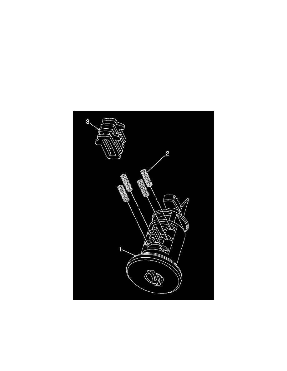
Instrument Panel Compartment Door Lock Cylinder
The instrument panel (I/P) compartment door lock cylinder uses 4 of the 10 key cut positions, 7-10 when counting from the key head. The tumbler
orientations alternate in adjacent locations with all 4 tumblers (3) located on the same side. A stainless steel retaining tumbler is used in the I/P
compartment door lock cylinder to retain the lock cylinder in the latch assembly and does not move when the key is inserted. The retaining tumbler is
located in the tumbler slot closest to the head of the cylinder assembly (1) and comes pre-installed in the cylinder.
1. Hold the uncoded cylinder assembly (1) positioned so the side with 4 tumbler spring holes is facing upward.
2. Insert one tumbler spring (2) each into the 4 tumbler spring holes.
3. The first tumbler to be loaded will be key cut position 7, the seventh number in the key code. Determine the cut depth at this position and install
the corresponding tumbler (3) into the tumbler slot nearest the front of the cylinder assembly (1), the end where the key is inserted.
4. In the same manner, determine the cut depth and corresponding tumbler and install the 3 remaining tumblers (3) into the tumbler slots located at
key cut positions 8, 9 and 10.
5. Snap the tumblers (3) into place with light hand pressure.
6. Check for correct tumbler loading by fully inserting the matching key into the cylinder (1). All tumblers (3) should be flush with the outside
diameter of the cylinder.