
CTS RWD V8-6.2L SC (2009)
Cruise Control Schematics (See: Diagrams/Electrical Diagrams)
Connector End View Reference
Component Connector End Views (See: Diagrams/Connector Views)
Description and Operation
Cruise Control Description and Operation (See: Description and Operation)
Electrical Information Reference
*
Circuit Testing (See: Testing and Inspection/Component Tests and General Diagnostics)
*
Connector Repairs (See: Testing and Inspection/Component Tests and General Diagnostics)
*
Testing for Intermittent Conditions and Poor Connections (See: Testing and Inspection/Component Tests and General Diagnostics)
*
Wiring Repairs (See: Testing and Inspection/Component Tests and General Diagnostics)
Scan Tool Reference
Control Module References (See: Testing and Inspection/Programming and Relearning) for scan tool information
Circuit/System Verification
Ignition ON, observe the scan tool Cruise Control Switch parameter. Verify the parameter changes each time the switch is pressed.
If the parameter does not change, refer to Cruise Control Malfunction (See: Cruise Control Malfunction).
Circuit/System Testing
Important: Refer to DTC B3794 (See: Powertrain Management/Computers and Control Systems/Testing and Inspection/Diagnostic Trouble Code
Tests and Associated Procedures/B Code Charts/B3794) before performing this diagnostic, if this code is set as current or history.
1. Ignition OFF, disconnect the harness connector at the steering wheel control switch-left.
2. Ignition ON, verify that a test lamp illuminates between the low reference circuit terminal 7 and B+.
‹› If the test lamp does not illuminate, test the low reference circuit for a short to voltage or an open/high resistance. If the circuit tests normal,
replace the BCM.
3. If all circuits test normal, test or replace the steering wheel controls switch-left.
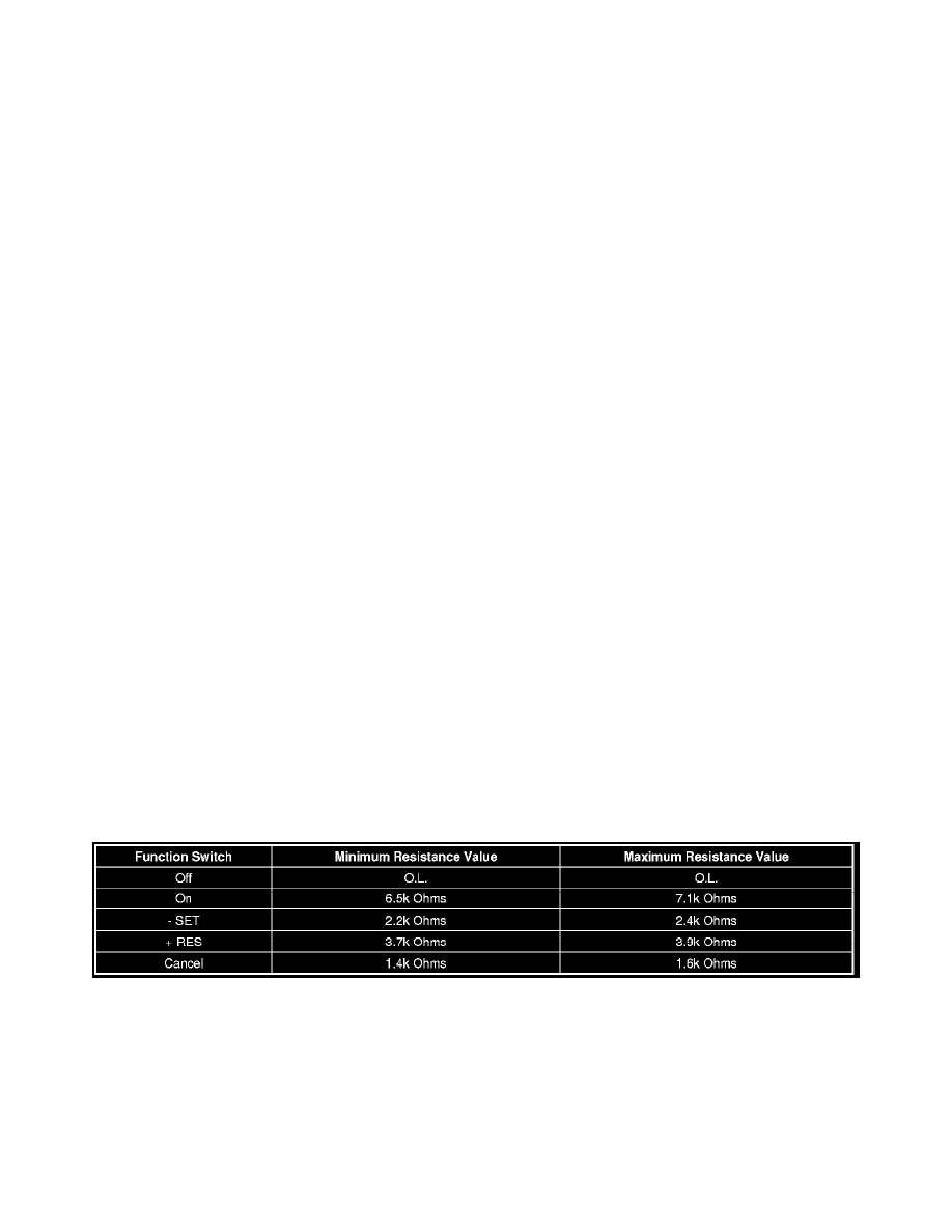
Component Testing
1. Disconnect the harness connector at the steering wheel controls switch - left.
2. Cruise control switch ON, measure the resistance between terminal 1 and terminal 2 while individually activation and holding each cruise control
function switch and compare the resistance reading to the values in the table below.
‹› If not within the specified resistance range, replace the turn steering wheel controls switch - left.
Repair Instructions
Perform the Diagnostic Repair Verification (See: Powertrain Management/Computers and Control Systems/Testing and Inspection/Diagnostic Trouble
Code Tests and Associated Procedures/Verification Tests and Procedures) after completing the diagnostic procedure.
*
Steering Wheel Control Switch Assembly Replacement (See: Accessories and Optional Equipment/Sensors and Switches - Accessories and
Optional Equipment/Steering Mounted Controls Assembly/Service and Repair)
*
Control Module References (See: Testing and Inspection/Programming and Relearning) for BCM replacement, setup, and programming
Cruise Control Malfunction